Contents
Gerber X2
Adding to Altium Designer’s existing ability to export a wide range of PCB design fabrication and assembly file formats, the new Gerber X2 format is now available for both individual and output job file generation.
Gerber X2 is a direct, and much advanced, evolution of the existing Gerber RS-274X standard and adds a large range of additional data for PCB fabrication and assembly. Compared to the RS-274X standard, the new Gerber X2 format includes critical information such as:
- Layer stack definitions
- Pad and via attributes
- Pick & Place and N.C. Drill Files
- and more…
A prime advantage of the new Gerber X2 format is backward compatibility with the old Gerber RS-274X standard. Being a multi-file standard, a target fab/assembly house that has not moved to the new standard can extract the traditional Gerber file elements as needed. This may be a significant advantage for those unwilling to tackle a major shift in fabrication file formats, or for fabrication houses with inflexible equipment and software.
The overall benefit of adopting the Gerber X2 format for transferring board design data to fabrication and assembly houses is the rich set of manufacturing data included in the file set, and the backward compatibility to the previous standard for a low risk upgrade path. With a full implementation at both ends of the CAD-CAM chain, the risks associated with data misinterpretation, file errors and variable data interpretation can be largely eliminated.
In short, both the Gerber X2 and IPC-2581 formats represent a new generation of board design to manufacture data transfer.
See the Ucamco website for further information.
Gerber X2 export
With a project PCB file loaded as the active document, the Gerber X2 file set can be exported by selecting File » Fabrication Outputs » Gerber X2 Files from the main menu. This opens an initial Gerber X2 Setup dialog to define the plot layers, drill options and general configuration applied during the export process.
The Gerber X2 output setup is similar to that of the standard Gerber output.
Setup configuration
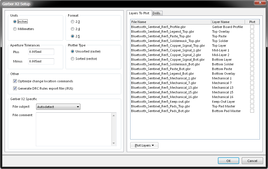
While Gerber X2 offers significantly advanced content and accuracy over the previous Gerber formats, its configuration is familiar and relatively straightforward in Altium Designer. The Gerber X2 Setup dialog provides a general Gerber setup section (left) and a tabbed Layer/Drill selection area, with the following options:
Units
The inherent units used in the generated file.
- Inches - Enable to choose imperial units where all work is done in mils (1/1000 inch).
- Millimeters - Enable to choose metric units and all work is done in millimetres.
Format
The selected format specifies the precision of the coordinate data, which is selected to suit the placement precision of the objects in the PCB workspace and/or fabricator preferences (normally set to the highest resolution: 2:5)
- 2:3 - The 2:3 format has a resolution of 1 mil (1/1000 inch).
- 2:4 - The 2:4 format has a resolution of 0.1 mil.
- 2:5 - The 2:5 format has a resolution of 0.01 mi.l
These options specify the numerical precision of the plot coordinates in the Gerber file. The first number represents the number of digits before the decimal point, and the second is the number of digits after the decimal point. With the 2:3 format for example, the largest number in the Gerber file could be 99.999 inches and the smallest number could be 0.001 inches (1 mil).
Plotter Type
Gerber files can be created with the data sorted by its position on the ‘film’, or unsorted. Sorting is only required by vector photoplotters and does not apply to modern raster-style plotters which create an initial image internally. If sorting is enabled Gerber generation may take an extended time.
- Unsorted (raster) - Use raster machine (default).
- Sorted (vector) - Use vector machine.
Aperture Tolerances
These option fields set the tolerance range used when matching apertures for each item in the plots. If no exact match for an item is available in the current aperture list, the software checks to see if a slightly smaller or larger aperture exists within this tolerance range and uses it instead.
If no suitable aperture exists within the tolerance range, the software will attempt to ‘paint’ with a smaller aperture to create the required shape. This requires that a suitable smaller aperture is available, and that this aperture can be used for ‘painting’.
- Plus - Define the positive tolerance for aperture matching.
- Minus - Define the negative tolerance for aperture matching.
Other
- Optimize change location commands – When this option is enabled, X or Y location data is not included if it does not change from one object to the next.
- Generate DRC Rules export file (.RUL) - Enable this option to generate a DRC Rules Export file. The report details the design rules defined for the source PCB document from which the Gerber data is being generated.
Gerber X2 Specific
- File Subject – Use the File Subject drop down list to nominate file type, which is included as a
Partattribute in the Gerber X2 outputs. The selections are:- Autodetect – Automatically assigns an attribute from the below list, based on the type of board file. For example, a PCB document containing a single board design will be assigned the
Singlepart attribute. - Single – A Single PCB.
- CustomerPanel – A board array or shipping panel.
- ProductionPanel – A working panel or fabrication panel.
- Coupon – A Coupon (performance test board associated with a main board design).
- Other – None of the above. In the file, a string appended to the attribute informally indicates the part.
- Autodetect – Automatically assigns an attribute from the below list, based on the type of board file. For example, a PCB document containing a single board design will be assigned the
- File Comment – Enter a comment that will be included as an attribute in the generated outputs.
Layers to Plot tab
The Layer to Plot tab listing provides check boxes for selecting which layers to plot in the Gerber X2 output for the current PCB document. The list can also display layer stackups for embedded board arrays. Any invalid layers (violating layers) in a layer stack are displayed in red.
- File name – The individual Gerber output file names. These use a naming convention that is indicative of the file’s function and use a
.gbrextension. All are based on the project name, layers and function, and use an underscore character as a descriptive separator. - Layer Name – The layer name that applies to each output file, as defined by the board’s layer stack.
- Plot – Layer selection checkboxes that enable a Gerber plot for that layer. Note that selections can be made collectively using the Plot Layers drop down menu (below the Layers To Plot list). The bulk plot selections can also be accessed from the right-click context menu.

Mass file selection is available for both the Layers To Plot and Drills listings.
Drills tab
The Drills Drawing tab listing includes the relevant drill files that will be generated for the current board design, which can be selected for generation on an individual or group basis.
All relevant Drill files are listed for the current board design.
This includes Drill drawing and Guide outputs. A drill drawing is a plot of the location of each drill site on the PCB, with each drill size plotted with a different symbol, whereas a drill guide plots marks each site with a small cross. Separate files are also available for plated and non-plated through-holes, and blind/buried vias if included in the design.
- File Name – The individual Drill output file names, constructed to comply with the Gerber X2 standard.
- Drill Layer Pair – The Layer Pair that is associated with the drill holes file. Layer Pairs are configured in the Drill Pair Manager within Altium Designer’s Layer Stack Manager.
- Plot – Layer selection checkboxes that enable a Gerber plot for that layer. Note that the checkbox associated with each file type heading (Drill drawing, Drill guide etc) toggles the selection of all files in that section. Selections can also be made collectively using the Plot Drills drop down menu (below the Drills list). The bulk plot selections can also be accessed from the right-click context menu.
Generated Plot/Drill files
Once generated directly from the PCB, the Gerber X2 output files will be added to the project and appear in the Projects panel under the Generated and Text Documents folders. By default the files are stored in the current project's source directory within a Project Outputs for... folder.
The generated Gerber output is also opened as a composite CAM document that can be edited and/or saved into the current project, and managed via the CAMtasitic panel.
Gerber X2 in OutJob
To include an Gerber X2 file export in a project OutJob, click on Add New Fabrication Output under the Fabrication Outputs entry and select Gerber X2 Files then the desired PCB document to export.
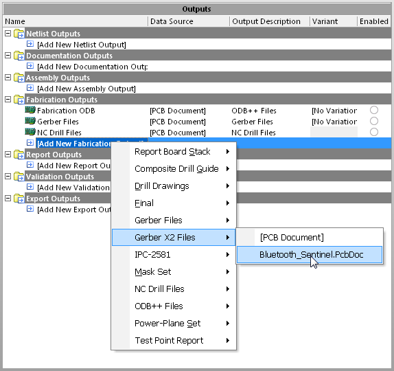
Gerber X2 export is available under the OutJob's Fabrication export options.
As with other Fabrication outputs, when the OutJob is run or manually instigated, the Gerber X2 file set will be exported as defined in the OutJob's Output Containers section.
This is to the configured Vault container and path, or the local/remote publishing target defined in the Data Management – Publishing Destinations entry in Altium Designer Preferences dialog (DXP » Preferences).
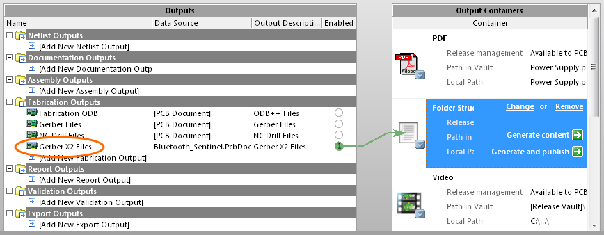
Generating Gerber X2 files to a local folder from within a configured OutJob.
See the Design to Manufacturing documentation for more information on OutJobs and publishing design data.