Contents
- Importing Files Using Quick Load
- Creating a New CAM Document
- Setting Up Import Options
- Importing CAM Files Using Quick Load
- Importing ODB++ Files Using Quick Load
- Importing NC Drill Files
- Importing Other File Types
- Importing DXF/DWG
- Importing a Standard PCB
- Importing DXF/DWG Files Using Custom Import Options
- Importing Mill Rout Files
- Exporting Files from the CAM Editor
- Exporting Gerbers
- Exporting Netlists
- Export Drill Files
This tutorial looks at importing and exporting a variety of CAM files using Altium Designer's CAM Editor (also referred to as CAMtastic®).
During this tutorial, we will investigate the Quick Load command by importing supplied Gerber and ODB++ files into the CAM Editor. Quick Load imports all traditional CAM documents (e.g. Gerber, ODB++, Aperture List Files (*.lst), NC Drill HPGL/HPGL2, and IPC-D-356 netlists) that are stored in a single folder.
The File » Import menu also includes separate commands that allow the import of selected Gerber, ODB++, netlist (IPC-356-D), NC Drill, Mill/Rout, DXF/DWG and HPGL/HPGL2 files. In this tutorial, we will use two of these commands to import an AutoCAD DWG file and a mill/rout file (.rte).
The import defaults in the CAM Editor are initially set for importing files exported from Altium Designer. The PCB example, 4 Port Serial Interface, that we use in this tutorial, was designed using Altium Designer. When importing files generated by other CAD/CAM programs, you should be aware of their output settings and edit the CAM Editor import dialogs accordingly. The Preferences dialog, accessed by selecting DXP » Preferences, allows you to set the defaults for importing and exporting Gerber files. This is necessary for Gerber RS-274D and NC Drill, but not for Gerber RS-274X, IPC-356-D, and ODB++ files.
We will also briefly investigate the export options available in the CAM Editor.
Importing Files Using Quick Load
The Quick Load command imports all CAM files located in a single folder. If your board has any holes, e.g. through holes or blind or buried vias, you must provide, at the very least, the signal layers (e.g. Gerber files for top and bottom) and one or more NC Drill file (Excellon 2 format).
First, we will create a blank CAM file, look at some setup options and then import the necessary files using Quick Load.
Creating a New CAM Document
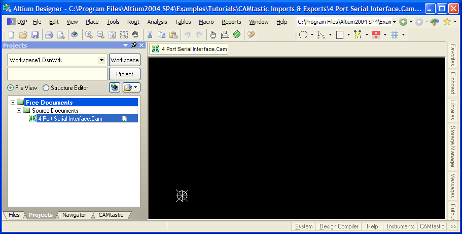
- Create a new CAM document by selecting File » New » CAM Document from the menu. A new blank CAM document,
CAMtastic1.Cam, opens in Altium Designer. - Save the document by selecting File » Save (shortcut: CTRL+S). Type in a name, for example, 4 Port Serial.Cam, browse to the location for your new CAM file and click OK.
Setting Up Import Options
Before importing the Gerber, NC drill and netlist files into the new CAM document, we need to set up some import options, such as the Gerber Import settings. These values are saved to the CAM DXP.ini file as defaults. Make sure you are in the CAM Editor view mode by selecting View » CAM Editor. The command will be grayed out if you are already in the CAM Editor. Alternatively, the current editing mode is shown at the top of the CAMtastic panel and can be toggled using the list.
- Select File » Setup » Import/Export. The CAM Editor - Import/Export page of the Preferences dialog opens. Make sure the default import format is RS-274-X, the extended Gerber format that includes the aperture definitions (embedded apertures). Click on the button displaying the format to change it, if necessary.
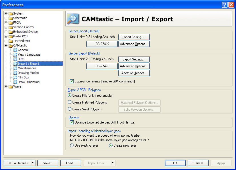
- Click on Import Settings to display the Gerber Import Settings dialog where you can set up the default import settings for Gerber files. Click OK to accept the default settings.

- We also must allow the CAM Editor to add new layers when importing data. We can specify if we want the CAM Editor to create new layers, even if layers with identical layer types already exist, or to use the existing layers. Using the existing layers should be very useful when loading data for more than one board in the same files using different steps in order to panelize the loaded PCBs onto the same CAM panel (multi-step panelization). In this tutorial, we want to create new layers automatically on import, so make sure the Create new layer option is enabled in the CAM Editor - Import/Export page of the Preferences dialog.
- Finally, we will check the filename extensions of the files that we are importing. To check the file extensions or add a new extension, click on the CAM Editor - Miscellaneous page of the Preferences dialog.
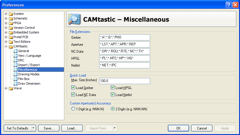
- The file extensions listed here determine the type of an imported file, e.g. a quick load of Gerber files will look for and load all files with an .A ,* .G * or* .PHO extension, for example. Add any additional extensions required, separated by a semi colon ; from the previous entry. In this tutorial, we can accept the default settings, so click OK.
Importing CAM Files Using Quick Load
We are now ready to import the Gerber, NC Drill and netlist files into the new CAM document. We will use the Quick Load option that imports all files found in the same folder in one go.
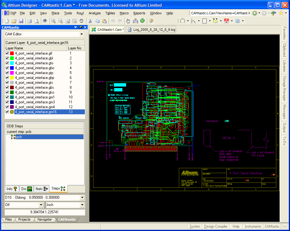
- Select File » Import » Quick Load. The File Import - Quick Load dialog displays. Browse to the \CAM Imports & Exports\Gerbers folder you extracted from the download ZIP mentioned at the start of this article, and click OK. Keep the default settings if your Gerbers are RS-274-X format and contain an FS (Format Settings) command, as is the case with our example files. Otherwise, you can specify the aperture format from the Detect Aperture Formats drop-down list, and click on the Gerber Options or Default Units buttons to display the setup dialogs. When you OK the Gerbers files will be loaded.
- When the Gerber files have finished loading, the Import Drill Data dialog displays.
- Click OK to accept the default settings in the Import Drill Data dialog and the NC files are imported into the CAM Editor and display in the design window along with a Quick Load Process Report log file. IPC netlist files are loaded last.
Note: If importing Gerber files generated from a P-CAD design, an error file, Load Error.rpt, will open displaying a message that Quick Load could not determine the statement 'T00 Invalid Tool Code' from the Drill/Rout File(s). T00 is an end of file marker for P CAD files, so this error file can be ignored and closed.
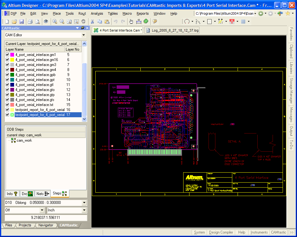
- Click the CAM button at the bottom of the workspace to open the CAMtastic panel, where you can view the layer names and other information. Press F1 over any panel to access the help.
- Save the file by selecting File » Save [shortcut: CTRL + S].
Importing ODB++ Files Using Quick Load
The ODB++ import option imports ODB++ files into the CAM Editor. If the NC drill data has been generated from Altium Designer's PCB Editor, you must separately import the NC drill data after the ODB++ import has been completed.
Other CAD/CAM packages should already have the drill hole data present in the ODB++ structure and so a separate import of the NC drill data is unnecessary.
- Select File » New » CAM Document from the menu. A new blank CAM document appears in the design window.
- Select File » Import » Quick Load. The File Import - Quick Load dialog displays.
- Click to open the Browse For Folder dialog and navigate to the \CAM Imports & Exports\ODB++ folder you extracted from the download ZIP mentioned at the start of this article, and click OK.
- Click OK to import the files and close the File Import Quick Load dialog. The Steps Table dialog then opens. This dialog displays all of the ODB++ steps that have been defined in the loaded ODB++ database for the current document. Steps are identified by Step Name and the Object Count associated with that step.
- Click OK to accept all default values for step assignment and the design is imported. A log file is also produced. The Steps tab in the CAMtastic panel will be refreshed and you can add or modify steps by right-clicking and selecting the appropriate command from the pop-up menu.
Importing NC Drill Files
Since we have imported ODB++ files generated by Altium Designer, we now we must import the NC drill information related to this design. Note that this must be done as a separate import after the ODB++ files have been imported.
- Select File » Import » Drill. The File Import NC Drill dialog displays. The file extension for NC Drill data created in the Altium Designer PCB Editor is .txt.
- Click to open the Browse For Folder dialog and navigate to the \CAM Imports & Exports\ folder you extracted from the download ZIP mentioned at the start of this article, and click OK. Back in the File Import NC Drill dialog select the file 4 Port Serial Interface.txt file. Click OK.
- The Import Drill Data dialog displays.
- Accept the defaults by clicking OK. The NC drill data will be imported on a separate layer whose layer name is based on the file name, e.g. _4_port_serial_interface.txt_. A log file is also produced.
- Save the file.
Importing Other File Types
You can use the File » Import menu options to import the following file types individually or as a selection: Gerber; ODB++; Netlist; Drill; Mill/Rout; DXF/DWG and HPGL/HPGL2.
If there are no embedded apertures included in the files you want to import, you can load an Aperture file using pre-determined template formats by selecting File » Import » Aperture File (using Wizard formats), or load a Custom Aperture Library file (.lib) by selecting File » Import » Custom Aperture Library File (.LIB).
For the remainder of this tutorial, we will look at importing DXF/DWG and Mill Rout files.
Importing DXF/DWG
You can import AutoCAD DXF/DWG files and each drawing layer will be converted to a different layer type. First, we will import a DWG using a default option and then using custom options.
Importing a Standard PCB
- Make sure you are in the CAM Editor mode, available from the list at the top of the CAMtastic panel. Otherwise, the Import DXF/DWG option is not available.
- Create a new CAM file by selecting File » New » CAM Document from the menu. A blank CAM document appears in the design window.
- Select File » Import » DXF/DWG. The Open Auto CAD DXF/DWG File dialog displays.
- Navigate to the \CAM Imports & Exports\ folder you extracted from the download ZIP mentioned at the start of this article, select the 4 Port Serial Interface.DWG file, and click Open. The DXF/DWG Import Wizard displays.
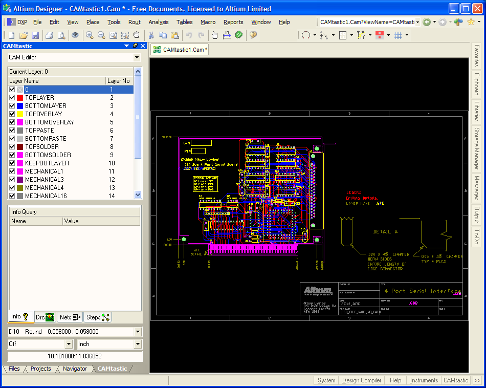
- For this tutorial, we are importing a DWG file of a PCB board, so select Standard PCB (Double-sided, etc.) and click OK. The import process commences and the resulting drawing will display in the design window upon completion.
- Save the file.
Importing DXF/DWG Files Using Custom Import Options
- Make sure you are in the CAM Editor mode.
- Create a new CAM file by selecting File » New » CAM Document from the menu. A blank CAM document appears in the design window.
- Select File » Import » DXF/DWG. The Open Auto CAD DXF/DWG File dialog displays.
- Navigate to the \CAM Imports & Exports\ folder you extracted from the download ZIP mentioned at the start of this article, select the 4 Port Serial Interface.DWG file and click Open. The DXF/DWG Import Wizard displays.
- In this part of the tutorial, we will import a DWG file and set up the options manually, so select Custom Import Options in the Wizard and click OK. The Import DXF/DWG dialog will then open.
- Each detected layer will automatically be selected for import. Four columns of options are available for each layer. Notice that the first layer name is 0 (zero). This is a critical layer when importing from AutoCAD, because all flashes are stored in this layer. The CAM Editor will distribute these into their relevant layers upon the import, so this Zero layer must be enabled.
- Enable the FRD (Flash Round/Donut Pads) option for each layer. When this option is selected, round and donut shapes are detected within your DXF/DWG files, and flashed apertures are automatically created.
- Set Units to Inches and Scale to 1.0.
- Click the Options button to display the Advanced Options dialog.
- Select the topmost OWP (Outline Width Polyline) mode and the Fill OWP option.
- Click on the Options tab, select Move Layer 0 block objects and Exclude trace endcap. Change the line width to 0.005 and Rectangle flash ratio to 6, if necessary.
- Press the Text options button in the Options tab and enable AutoCAD SHX in the Default Font Style tab. The font should be set to romans.shx
If this is not visible, press the Browse button to locate the shxfont folder. In the Text Line Width / Fill Mode tab, select Use same line width for all and enter 0.001 as the line width value.
- Click OK until all dialogs are exited and the DWG file is loaded into the CAM Editor.
Importing Mill Rout Files
This command is used to import a Mill/Rout data file into the current document.
- Create a new CAM file (File » New » CAM Document) and select File » Import » Mill/Rout. The File Import - Mill/Rout dialog displays.
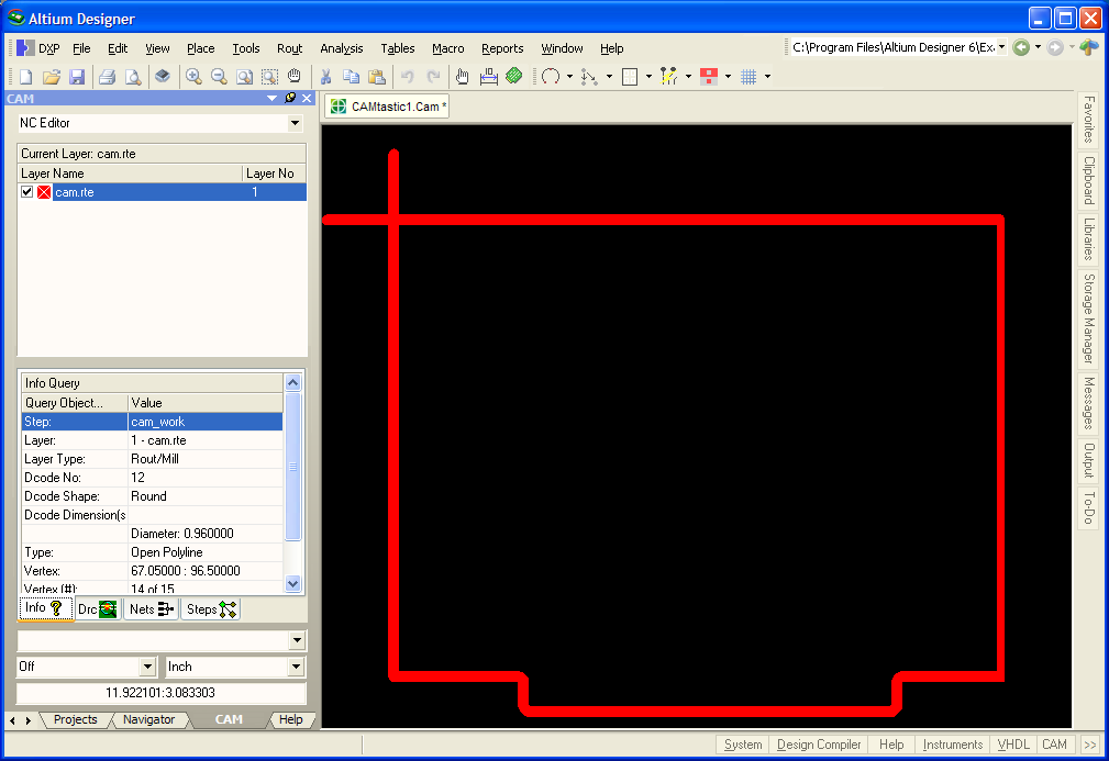
- Click to open the Browse For Folder dialog and navigate to the \CAM Imports & Exports\ folder you extracted from the download ZIP mentioned at the start of this article, and click OK. Back in the File Import _Mill/Rout dialog select the file Cam.rte file. Click OK.
- The Import Mill/Rout Data dialog displays, accept the defaults by clicking OK. The data will be imported on a separate layer whose layer name is based on the filename, e.g. cam.rte. A log file is also produced.
- Save the file.
- If you wish to modify the Mill Rout layer, you must be in the NC Editor mode. Select View » NC Editor and the Rout menu options will become available.
Exporting Files from the CAM Editor
All CAM Editor outputs are generated through the File » Export menu. You would need to export files when you have made modifications to the original outputs, or if you require the Test Point or NC Drill data saved in Gerber format.
The following export options are available when in the CAM Editor:
- Gerber
- Netlist
- IPC-D-350
- Save Drill
- Mill/Rout
- DXF
- Part Centroids
- Aperture List
- Library
- Bitmap (*.bmp).
You must be in NC Editor mode to access the Drill export option.
Exporting Gerbers
- Open the CAM document you created by importing Gerber files earlier in this tutorial (4 Port Serial Interface.CAM). Select View » CAM Editor.
- Check the default export settings. Select File » Setup » Import/Export. The CAM Editor Import/Export page of the Preferences dialog displays. Make sure the default export format is RS-274-X , the extended Gerber format that includes the aperture definitions (embedded apertures).
- Click the Export Settings button to display the Gerber Export Settings dialog where you can set up the default export settings for Gerber files.
- Click OK to accept the default settings. Click OK to close the Preferences dialog.
- Select File » Export » Gerber. The Export Gerber(s) dialog displays.
- Accept the default settings by clicking OK. The Write Gerber(s) dialog displays.
- Select the Gerber files you want to export by enabling them in the dialog. Alternatively, select the files for exporting using the right-click menu selections or use the SPACEBAR to toggle the selection.
Note that the OK button is disabled if the format of the output file name is incorrect. The output file names must not contain any spaces or capitals and must not exceed 64 characters. Double-click on a filename to type in a new filename. To change the filename extension, select the Gerber filename and then right-click and select File Extensions. Enter a new extension (three characters maximum) in the Enter Value dialog and click OK.
- Choose a location for the exported files by clicking the Browse for Folder button. Click OK and the files are exported.
Exporting Netlists
You can export netlists in two formats. Use the File » Export » Netlist command to export a netlist in IPC-D-356 format (.net). Use the File » Export » IPC-D-350 to export an IPC-D-350 netlist (.ipc). You must have a netlist extracted from the imported data before you can use these commands.
- Make sure you are in the CAM Editor. If you have not already extracted the netlist, select Tools » Netlist » Extract.
- Select File » Export » Netlist. The Write IPC-D-356 dialog displays.
- Select the .net file and choose a location and filename for this netlist (testpoint) report. Click OK and the file is exported.
Export Drill Files
- Select NC Editor mode (View » NC Editor).
- Select File » Export » Drill. The Export Drill Data dialog displays.
- Accept the defaults by clicking Save. The Write Drill dialog displays.
- Choose a location and the filename (.drl) for this drill export and click OK. The drill files are exported to the nominated location.