A Walk Through the Board Design Release Process
Contents
- Design Project - Initial Preparation
- Create a New Design Repository
- Through Altium Designer
- Through an Altium Vault
- Add Your Project to the Design Repository
- Connect to an Altium Vault
- Define Vault Folder Structure
- Item Naming Scheme
- Create Target Items
- PCB Project Configurations and Output Job Files
- Define Output Job Files
- Specify Output Locations
- Define PCB Project Configurations
- Release a Configuration of the Design
- Trial Run - Design Mode
- Actual Release - Release Mode
- Access Released Data
Parent article: Board Design Release
Altium's Design Data Management system includes a range of technologies that combine together to allow you to pass data from the design domain to the production domain in a pain-free, streamlined, and automated fashion – generating data output of the highest integrity.
A key element of this system is a powerful board design release process. This process is automated, enabling you to release your design projects or, more specifically, defined configurations of those projects, without the risks associated with manual release procedures. When a particular configuration for a project is released, a snapshot of the design source is taken and archived along with any generated output. Release data is stored as a revision of a specific Item in a target Altium Vault. The Item is the entity within the vault to which the configuration is mapped, and which represents the physical object that will be 'realized' by the supply chain.
This article looks at how you prepare the system for release of your board design, how you initiate a release, and how you can 'get at' your generated release data upon successful completion of a release. Tutorial-like, but not rigidly so, think of this article as more of a conversational 'walk through' of the system – providing an overview of the system's key elements and how they are defined, with links out to more in-depth articles where appropriate.
Design Project - Initial Preparation
The first thing is to ensure that your design project is added to a version control repository, or Design Repository, as it's known within the system. Of course, you can still release a design project that is not under version control, but by using a version-controlled Design Repository, you have the integral assurance that no revision of a design is ever lost, allowing for safe collaboration on the same design between members of a team that can be geographically diverse in their locations. The very nature of the version control system provides an audit trail for the design. Full accountability arises through transparency of who changed what, in which source document, and when.
Create a New Design Repository
Related article: Securing Design Source Inside a Design Repository
A Design Repository can be created in two ways - either through Altium Designer, using built-in or external version control, or through a suitably licensed installation of the Altium Vault.
Through Altium Designer
Both Subversion (SVN) and Concurrent Versions System (CVS) version control providers are supported for implementation of Design Repositories. However, Subversion is the recommended provider as it is widely and freely-available, and in true keeping with its unified nature, Altium Designer includes Subversion capabilities built-in. Version control providers are enabled and configured on the Data Management – Version Control page of the Preferences dialog (DXP » Preferences).
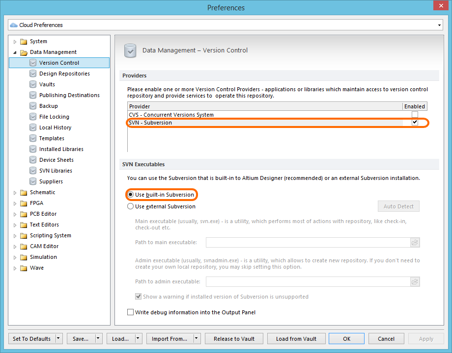
Version-controlled Design Repositories can be created and connected to the system when using either Subversion or CVS as the version control provider. The built-in Subversion is, by default, ready to use from the outset.
Creation of new Design Repositories from within Altium Designer is performed from the Data Management – Design Repositories page of the Preferences dialog. Simply click the Create New button and choose the type of repository you wish to create – either SVN or CVS - from the associated drop-down menu. The applicable creation dialog will appear. For an SVN repository, this is the Create SVN Design Repository dialog. Use this to give the vault a meaningful name, specify a default checkout path, and specify the location for the repository. If a folder is specified that does not currently exist, it will be created for you.
With all settings specified as required, click OK. The repository will be created at the nominated location and a connection to that repository from Altium Designer made. An entry will appear for it in the listing of Design Repositories back on the Data Management – Design Repositories page of the Preferences dialog.
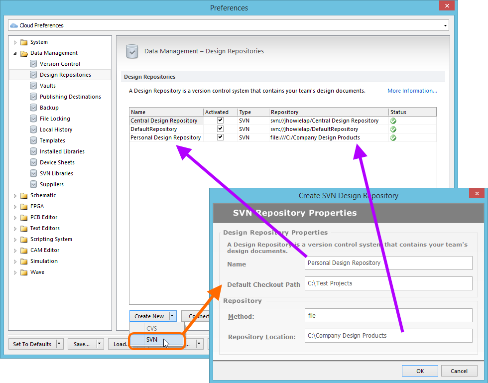
Example newly created SVN Design Repository, appearing within Altium Designer as Personal Design Repository.
Through an Altium Vault
Related article: Altium Vault - Local Version Control Service
An appropriately licensed Altium Vault installation provides localized (and centralized) version control, courtesy of its Version Control Service - essentially an SVN server (version 1.8).
Repositories can be created through the Altium Vault's local SVN server, or external repositories can be connected to. Together, all repositories are centrally managed through the VCS page of the vault's browser-based interface.
To add a Design Repository, simply click the Add Repository button, located at the top-right of the VCS page. The Repository Properties window will appear, use this to define the repository. The properties required depend on whether you are creating a new repository using the local VCS service, or linking to an existing, external repository:
- New - simply give the repository a name and a description.
- Existing - in addition to a name and description, you need to supply the URL to the repository, and your credentials (User Name, Password) to access that repository.
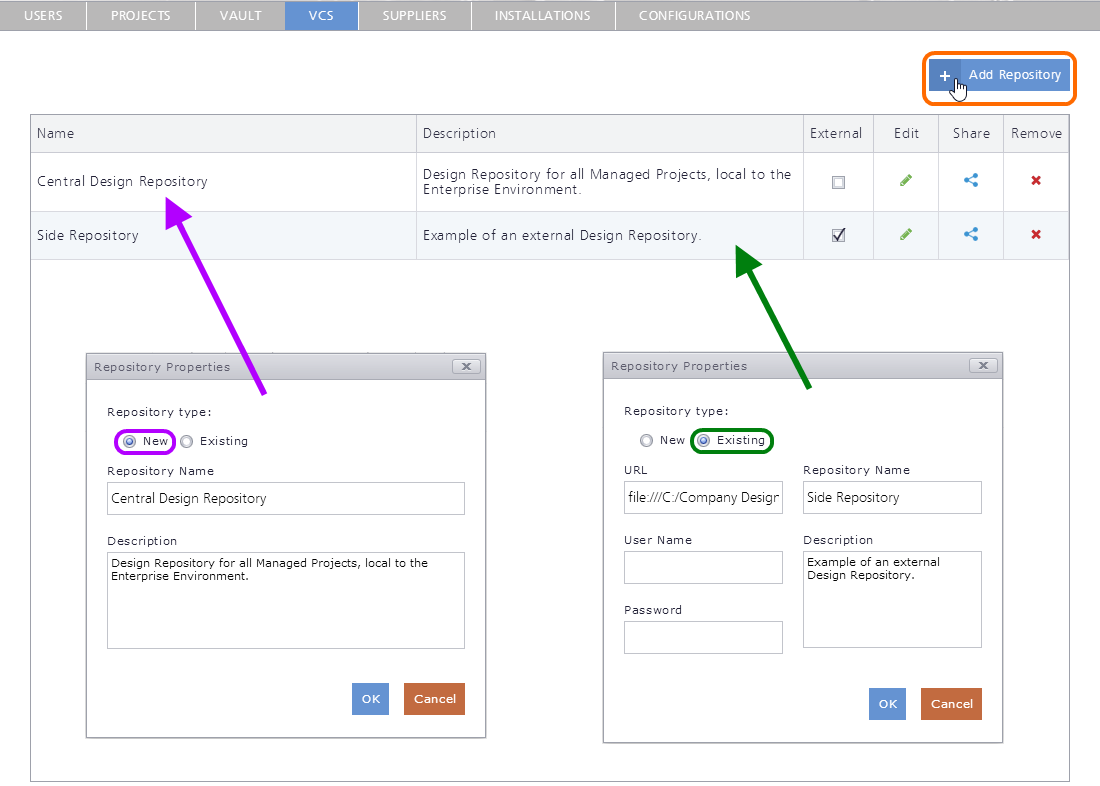
Create a new SVN-based Design Repository, or link to an existing one.
Design Repositories defined through the Altium Vault are populated to the client automatically during login, so users do not have to worry about urls, protocols, password etc. A repository is simply configured once, on the server, and shared with the intended users as required.
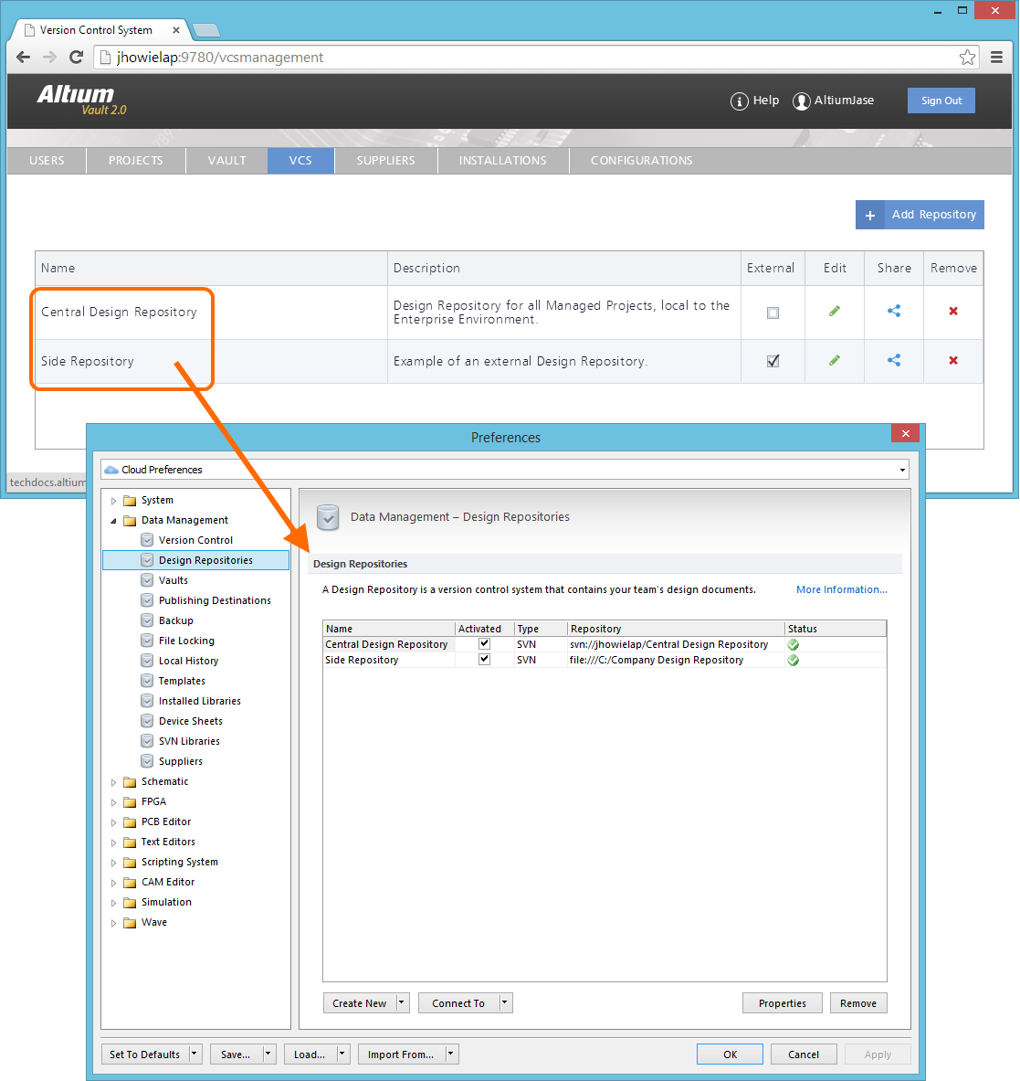
Centrally define access to your organization's Design Repositories. Repositories can be internal to the Altium Vault installation, defined using the local VCS service, or external through use of Altium Designer's built-in SVN, or third party SVN service. Access control is performed through the VCS page of the Altium Vault's browser-based interface. When a user signs in to the Altium Vault, the Design Repositories available to them will automatically be added to the Data Management - Design Repositories page of the Preferences dialog.
Add Your Project to the Design Repository
Related article: Version Control and Altium Designer
With your centralized storage repository – your Design Repository – created, you now need to add your design project and any dependencies (e.g. device sheets, harness definition files, annotation file) to that repository. This can be performed using version control commands from within Altium Designer – from the Storage Manager panel or Projects panel – or externally, from within the repository itself.
For this walk-through, let's add the reference design project for the Bluetooth Sentinel:
- Open the
Bluetooth_Sentinel.PrjPcbexample project (from the installation location you chose for shared documents). - Right-click on the project in the Projects panel and choose Version Control » Add Project Folder To Version Control from the context menu.
- The Add to Version Control dialog that appears presents a drop-down listing of all connected and activated Design Repositories. As this is a standard design project and not a managed project, we could add it to any design repository - created through Altium Designer, or through the Altium Vault. In this case, let's select one of the repositories we created through the vault's Local SVN service –
Central Design Repository.
The folder hierarchy within the chosen Design Repository is presented to you in the Folders region of the dialog. Either specify an existing folder into which to add the design files, or create a new folder using the New Folder button. In the latter case, a folder will be added at the specified position within the repository's folder hierarchy, named after the source folder containing the project.
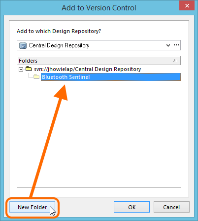
Specify the folder within the repository to store the project.
- With the target folder specified, click OK – you will be presented with a second Add to Version Control dialog. Simply select the files to add to the repository and click OK. The Projects panel will now show that the project and files are
Scheduled for addition, denoted by a blue cross icon ( ).
).
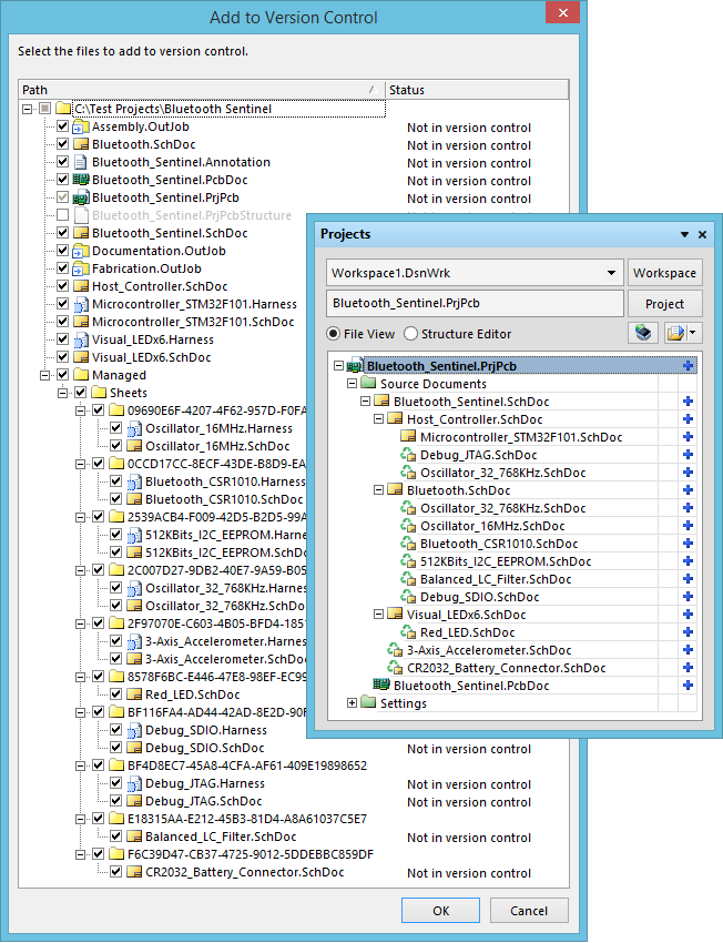
The project files are now in a state to be committed to the Design Repository.
- Now right-click on the project in the Projects panel and choose Version Control » Commit Whole Project. You will be presented with the Commit to Version Control dialog. Simply select the files you wish to commit to the Design Repository and click OK. Once added, the Projects panel will reflect the fully synchronized state that exists between the files in the repository and the local working copy.
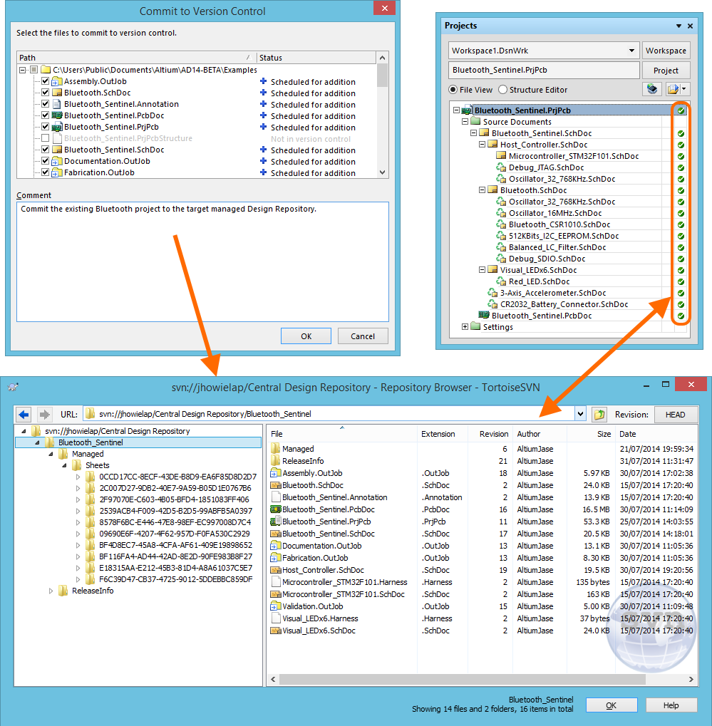
Example project added to the created Design Repository, in this case the Bluetooth Sentinel reference design.
Connect to an Altium Vault
Related article: Altium Vault
With the project added to the Design Repository, we can go ahead and connect to an Altium Vault. An Altium Vault is simply a centralized storage system into which all release data – for each target Item – is stored. In the vault, each Item is stored as a series of revisions. Each revision contains documentation, generated at release time, that is inclusive of detailed instructions needed to build that specific Item. Each time a new release of the design data for a particular Item is required, a new revision of that Item is created in the vault, ready to accept (store) the generated data.
Accessing your Altium Vault from within Altium Designer is a case of connecting to the vault, and also signing into the vault platform - giving access to other services delivered through the vault's installation, in addition to the vault service itself. Connecting and signing in to the Altium Vault can be done in the following ways:
- Use the Sign in Altium Vault command from the DXP menu.
- Add a connection to the vault from the Data Management - Vaults page of the Preferences dialog.
- Click the Sign in Altium Vault control, on the System — Altium Vault page of the Preferences dialog.
Irrespective of method used, the connected vault will be apparent in the Vaults listing, on the Data Management - Vaults page of the Preferences dialog.
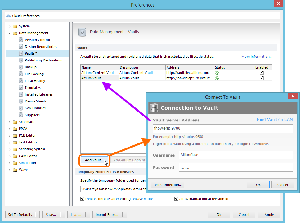
Example of a connected Altium Vault, appearing within Altium Designer as Altium Vault.
Define Vault Folder Structure
Related articles: Vaults Panel, Working with the Vaults Panel
Having connected to an Altium Vault you now need to define it, in terms of its internal structure and the various Items it is to contain the data for. In terms of releasing a board design, these will typically be Items representing the Blank Boards and Assembled Boards that you will ultimately manufacture. Interaction with a vault is performed through the dedicated Vaults panel. This is a system panel (accessed from the System panel-access button at the bottom-right of the main design window) that enables you to browse and manage your connected vault(s).
Interact with a connected Altium Vault through the Vaults panel. The panel allows you to define the structure of the vault, and Items that reside within.
In the Vault Folders region of the panel, use commands on the right-click menu to define a series of folders and sub-folders in which to organize Items – bringing a sense of logical order to the world. Items themselves are created using the Create Item command, on the right-click menu for the Items region of the panel.
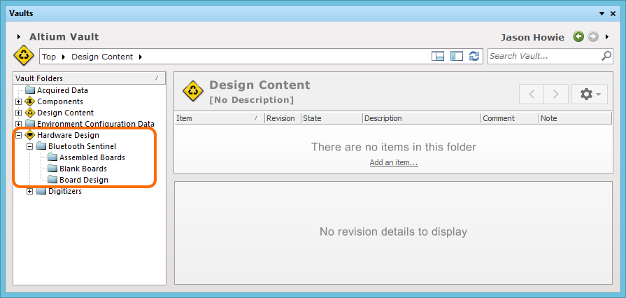
For our Bluetooth Sentinel design project, we will create three Items – one to represent a blank board, one to represent an assembled board, and one to represent the board design itself. Let's go ahead and define a folder structure:
- Right-click inside the Vault Folders region of the Vaults panel and choose the Add Top Level Folder » altium-production-release-zone command to define a top-level category in the overall structure. The Add Top Level Folder dialog will appear, from where you can enter a meaningful name for the category. As this folder will ultimately hold the data for all board designs that are released, let's call it
Hardware Design. - To add depth to the structure, simply right-click on an existing folder and choose the Add Subfolder » generic-folder command. Use the Add Subfolder For <ParentFolderName> dialog to name this new folder. Let's call it
Bluetooth Sentinel. -
Let's also create further sub-folders for the different types of released Item. This is purely optional, and all Items could quite happily be created in a single folder, it's rather more to provide a visual clue when browsing the folder structure. Let's add further sub-folders called
Folders defined ready within the vault. By using the concept of top-level 'zones' of content within a vault, you can have separate areas for componentBlank Boards,Assembled Boards, and Board Design respectively.
management, design content management and production release data.
Item Naming Scheme
Another important aspect of the parent folder is the Item Naming Scheme employed for it. This defines the format of the unique ID for each Item created in that particular folder. Several default example schemes are available, utilizing the short-form code for either the folder type or the content type. Using a default naming scheme, the software will automatically assign the next available unique ID, based on that scheme, having scanned the entire vault and identifiers of existing Items.
A custom scheme can also be defined for a folder, simply by typing it within the field, ensuring that the variable portion is enclosed in curly braces (e.g. Assembled-001-{J000}).
For this walkthrough, we'll set the Item Naming Scheme for each of our sub-folders to be $CONTENT_TYPE_CODE-001-{0000}.
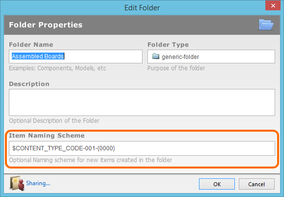
The Item Naming Scheme of the parent folder is applied to the unique ID for each
Item created in that folder.
Create Target Items
Having defined folders within the vault as required, you can proceed to create Items in the vault. To create an Item, simply click on the folder into which you wish to effectively store the Item, right-click in the Items region of the panel and choose the Create Item command. A further sub-menu will allow you to choose the particular type of Item, based on the type of data content it is to hold. The Create Item dialog will appear, providing all controls necessary to fully define the Item.
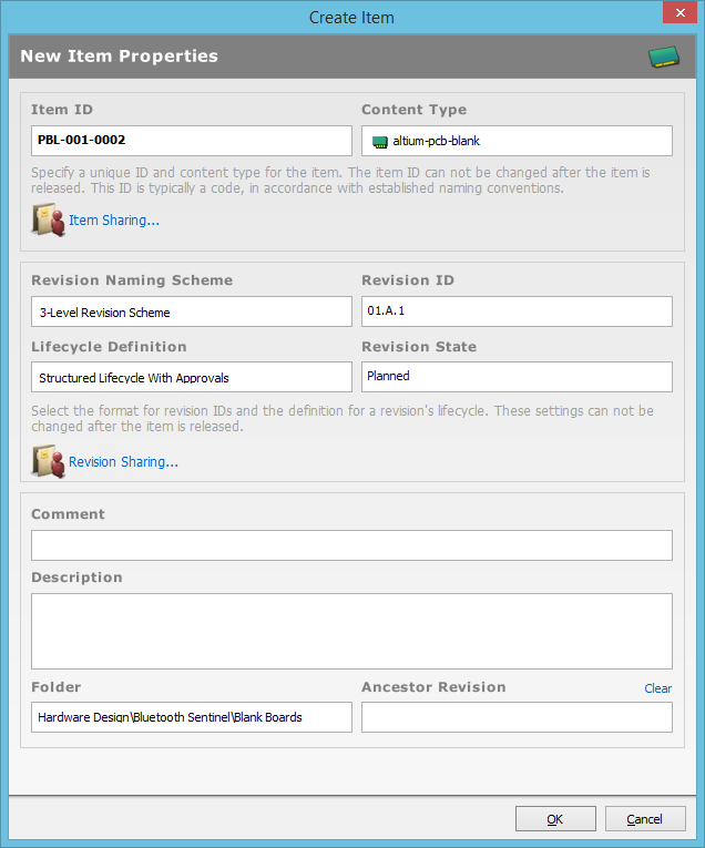
Create and define an Item using the Create Item dialog.
The key property for an Item that we are interested in at this stage is the Item ID – the unique ID for the Item. It is through this ID that a configuration of a project on the design side is able to be mapped to the target Item in the Altium Vault. The ID itself is typically a code, in accordance with established naming conventions. The Item ID can not be changed after the Item is created.
Let's go ahead and create the three Items for the Bluetooth Sentinel design:
- Click on the
Bluetooth Sentinel\Blank Boardsfolder in the Vaults panel, then:- Right-click in the Items region and choose Create Item » altium-pcb-blank.
- Leave the Item ID as the auto-generated/assigned entry (based on the folder-level Item Naming Scheme). This will be different, depending on the next unique ID available in your vault.
- Set the revision naming and lifecycle definition schemes as required. For this walk-through, let's set the Revision Naming Scheme to be
3-Level Revision Schemeand the Lifecycle Definition to beStructure Lifecycle With Approvals. - Add a Comment – let's say Bluetooth_Blank.
- Add a Description – let's say
Blank Board for the Bluetooth Sentinel. - Leave all other fields at their default settings.
- Click on the
Bluetooth Sentinel\Assembled Boardsfolder, then:- Right-click in the Items region and choose Create Item » altium-pcb-assembly.
- Repeat the process in 1, but this time enter a Comment of
Bluetooth_Assyand a description ofAssembled Board for the Bluetooth Sentinel.
- Click on the
Bluetooth Sentinel\Board Designfolder, then:- Right-click in the Items region and choose Create Item » altium-pcb-design.
- Repeat the process in 1, but this time enter a Comment of
Bluetooth_Designand a description ofBoard Design for the Bluetooth Sentinel.
We now have our Items defined ready in the vault, each with an initial revision, sitting in the Planned state – ready to accommodate release data!
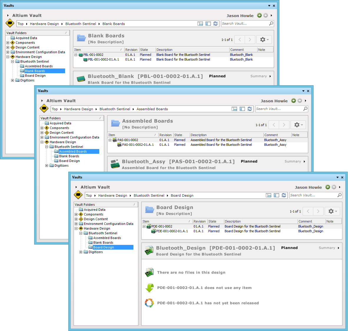
Items created, defined and with initial planned revisions to accept data.
PCB Project Configurations and Output Job Files
With the project in the Design Repository, it’s now time to prepare it for the release management system, but before doing so it’s important to understand just how the data in the design maps to the outputs required to manufacture the items you want to produce. This is managed through a concept known as the PCB Project Configuration.
Put simply, a PCB Project Configuration, or simply a Configuration, is used to map the data in the Design Area to the Item we want to produce. Each of these Items is uniquely identified by an Item ID, and each Item corresponds to the sort of thing one might expect to find on a product-level bill of materials – such as a bare board, assembly, and different assembly variants. Each are examples of different Items and each would have its own unique Item ID.
The PCB Configuration serves as a blueprint to map the data in the Design Area to the files required to produce some specific item.
The Configuration allows us to define the blueprint by which the source data in our project is converted to the outputs required to manufacture each unique Item. Each project therefore will generally have at least 2 configurations, one for the bare board and one for the assembled board. Different assembly variants would also each have their own configurations and thus map to their own unique Items.
The use of configurations requires a change in the way Output Job files are managed in a project. Where historically Output Job files might contain all of the outputs you want to produce, defined in a single *.OutJob file, for the release management system it’s best practice to separate assembly and bare board outputs into at least 2 (or more) output job files (with each file containing only the outputs specific to the type of finished goods – whether bare board or assembly – that you want to produce). Also, because the release management system supports validation of the design, as a part of the release process, it’s recommended you have at least one Output Job file that specifically defines the validations you’d like performed on the design while running the release flow.
Define Output Job Files
Related article: Understanding and Using Output Jobs
The Bluetooth Sentinel reference design project has three Output Job files already defined:
Assembly.OutJob– catering for assembly-based output.Fabrication.OutJob– catering for fabrication-based output.- Documentation.OutJob – catering for other documentation output.
We will also add a fourth – Validation.OutJob – which we will use to generate ERC, DRC and a Differences report.
Once the output generators are defined as required in each file, ensure to commit the changes from the local working folder back into the master fileset in the Design Repository.
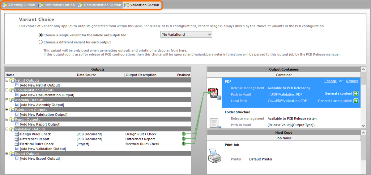
Separate and distinct Output Job files, including one that defines validation reports that will be run during the release process.
Specify Output Locations
Related article: Enhanced Output Path Definition in Output Job Files
The outputs defined in an Output Job file can be published into various types of output container, depending on the type of media being published. When publishing to PDF, generating files, or generating video, you have advanced control over where the outputs generated in these containers are located.
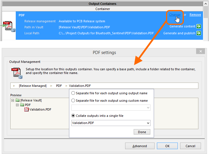
Accessing output location controls, in this case for a PDF output container.
Define PCB Project Configurations
Related article: PCB Project Configurations
So where are we up to. We have our Bluetooth Sentinel design project resident in a version-controlled Design Repository. We have our target Items defined and sitting ready in our Altium Vault. We need some way of mapping our design project to those Items. Remember, a PCB project is parametric in nature, enabling a single design project to be the source of multiple real-world production Items – the tangible products that are made and sold. Providing a formal configuration structure, to map from source PCB project to these Items in the vault, Altium Designer employs the concept of PCB Project Configurations.
Configurations are part of the actual design project and provide the link from the design world to the manufacturing world. Each configuration represents an Item that we want to build in the real world, defining the data that will be required by the supply chain to actually build that Item. When we release a design project, we are in fact releasing a configuration of that project. The generated 'release data' is stored in a revision of the target Item specified as part of that configuration.
All definition and management of configurations for a PCB project is performed from within the Configuration Manager dialog (Project » Configuration Manager). The Bluetooth Sentinel project already has three configurations added, as shown below.
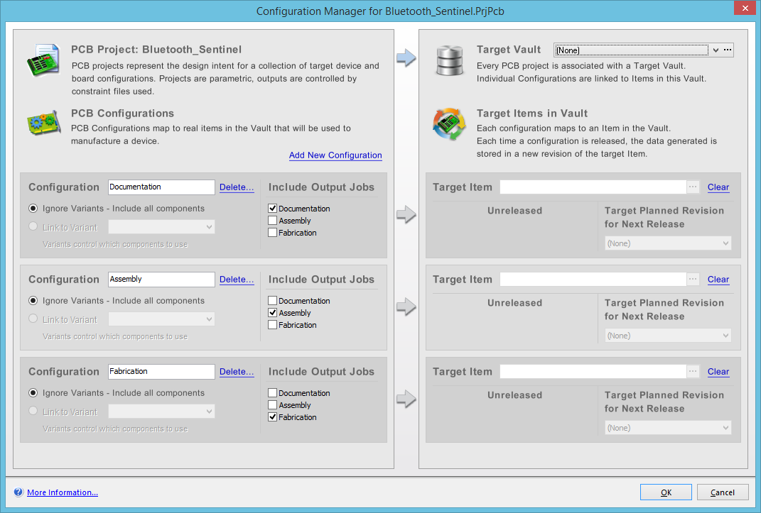
Initial appearance of the Configuration Manager for the Bluetooth Sentinel reference design.
First things first, we need to specify a target Altium Vault – release data could be stored in any vault, and if we had multiple vaults defined, we need to make sure that the design references the correct vault. Simply use the drop-down at the top-right of the dialog to select your Altium Vault. In this example, the name of the vault – as seen by Altium Designer – is called Altium Vault. Select the name that you have given your particular vault.
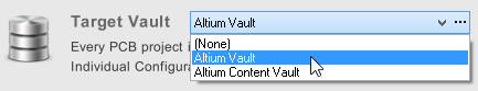
Targeting the required vault.
Now we need to define the configurations that we need for our project, and specify the target Items that they are to map to in the vault. The Configuration Manager dialog is divided into configurations on the left, that map to target Items on the right. Each unique configuration must map to a unique Item in the target vault. We require three configurations, to map to the following types of Item that we have created previously in the vault:
- Blank Board (altium-pcb-blank) – this type of Item is used to produce a fabricated bare board, containing no components.
- Assembled Board (altium-pcb-assembly) – this type of Item is used to produce a Blank Board Item that is populated with components in accordance with a generated BOM.
- PCB Design (altium-pcb-design) – this type of Item is essentially used to gather together all documentation - fabrication, assembly, and any other documentation - in a single place, a released 'master' copy of the design as it were.
Let's consider the configuration needed for the blank board:
-
On the left side (Configuration), rename the existing Fabrication configuration to
Defined configuration needed to generate the data to build the fabricated bare-board.Blank Boardand leave the option to Ignore Variants enabled. For the blank board configuration, we need to assign theFabricationandValidationOutput Job files, and so simply check their corresponding check boxes.
-
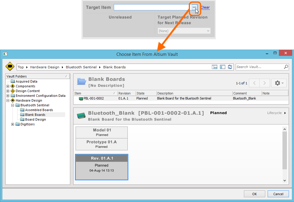
On the right side (Target Item), we need to specify which Item in the vault is to be "built" using the data generated from the configuration at release time. Click on the
Mapping the Blank Board configuration to the blank board Item (PBL-001-0002) defined in the vault. button at the right of the field. This will give you access to the Choose Item dialog. This dialog essentially presents a view of the target vault, and allows you to drill down within the folder structure you have defined to the particular Item you want to map the configuration to. Choose the Item PBL-001-0002in theHardware Design\Bluetooth Sentinel\Blank Boardsfolder. Note that if you hadn't created an Item already in the vault, you can do so through this dialog, on-the-fly as it were.
- In order to release a configuration, the revision of the Item into which the release data is to be stored must be in the
Plannedstate. That is, it must be ready to accommodate that release data. Use the drop-down list associated to the Target Planned Revision for Next Release field to choose a planned revision to use. As our Item only has a single planned revision, it will be chosen automatically –01.A.1.
Now we need to define a configuration (and the Item to which it maps) for the assembled board:
- On the left side (Configuration), rename the Assembly configuration to
Assembled Boardand leave the option to Ignore Variants enabled – so we use the full complement of components in the design, and not a subset. In terms of Output Job files for this configuration, we need to assign theAssemblyandValidationfiles, and so simply check their corresponding check boxes. - On the right side (Target Item), we simply repeat the previous process of specifying the target Item to map the configuration to, and a planned revision of that Item to use for the release. Specify the Item to be
PAS-001-0002– the revision field will automatically be filled with the initial planned revision,01.A.1.
And finally, let's define the third configuration for the design itself:
- On the left side (Configuration), rename the Documentation configuration to
PCB Designand leave the option to Ignore Variants enabled. In terms of Output Job files for this configuration, we need to assign all files, as this Item will hold the full spectrum of documentation generated for the design. Simply check the corresponding check box for all OutJob entries. - On the right side (Target Item), we simply repeat the previous process of specifying the target Item to map the configuration to, and a planned revision of that Item to use for the release. Specify the Item to be
PDE-001-0002– the revision field will automatically be filled with the initial planned revision,01.A.1.
Our three configurations for the Bluetooth Sentinel design project are now fully defined, and mapped to planned revisions of the unique Items we have created in the vault.
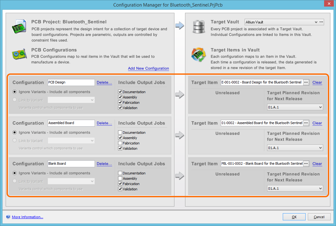
Our configurations for the Bluetooth Sentinel design fully defined.
One final thing to do before we proceed to the PCB Release view and ultimately to the release process itself, and that is to SAVE AND COMMIT LOCAL CHANGES TO THE DESIGN REPOSITORY. The importance of this cannot be stressed enough, and this is why the system requires all files to be checked in and up to date before releasing. Of course, you can synchronize at any stage and the PCB Release view will chase you about it, but it is good to get into the habit of committing changes at the time you make them.
Release a Configuration of the Design
Related article: Releasing a Design with the PCB Release View
The PCB Release view is the graphical interface to Altium Designer's PCB Process Manager – used to perform the board design release process – and presents a high-level 'Dashboard' that operates in two modes: Design Mode and Release Mode.
Access to the PCB Release view is made using the View » PCB Release View command, or by clicking the ![]() button on an editor's Standard toolbar.
button on an editor's Standard toolbar.
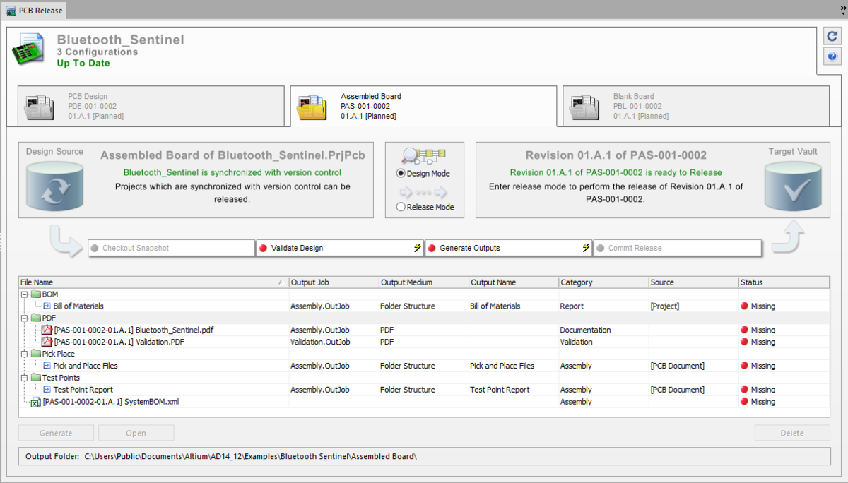
Initial appearance of the PCB Release view showing our Bluetooth Sentinel design project.
The view shows a single tab for our project (Bluetooth_Sentinel) and three sub-tabs for each of the configurations we have defined for that project (PCB Design, Assembled Board, and Blank Board). Let's look at releasing the Assembled Board configuration – click the tab for this configuration to make it the active configuration.
We have already synchronized our local working copy of the project with that in the Design Repository, and specified the target Item in the vault that the Assembled Board configuration is to map to – including a specific planned revision of that Item. The PCB Release view, initially in Design Mode, reflects that our project is synchronized with version control in the Design Source region, and in the Target Vault region, the revision of the Item referenced in the active configuration is indeed ready to release. Everything is in a 'green state' ready to release.
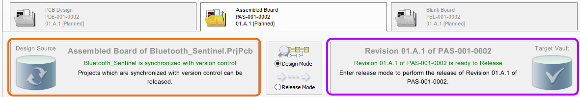
Green on both Design Source and Target Vault sides - good to go!
Each configuration has an associated Process Flow. In its entirety, this flow represents the board design release process – getting the design from the Design Repository, processing the chosen configuration of it, and committing generated release data into the referenced Item Revision in the nominated vault.
Trial Run - Design Mode
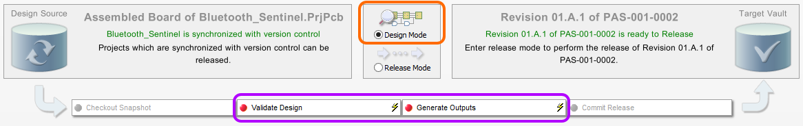
Notice that only stages 2 and 3 of the flow are active and enabled in Design Mode – Validate Design and Generate Outputs. These two stages are the 'meat' of the flow and their successful running is crucial to the board design release process. If either of these stages fails, the release fails – simple as that. So within Design Mode, access to these stages gives you arguably the most valuable pre-release checking aid possible.
You have the option to trial run the validation and output generation stages while in Design Mode - one last check that the design will pass muster with checks such as ERC and DRC, and
that those generated files are all as they should be to get the Item built as you designed it!
- Click the Generate Outputs stage of the flow. This will run the Validate Design stage, followed by the Generate Outputs stage. The state in each output's Status field will reflect when that output is running and then the result once generation is complete.
- If any failures occur, simply return to the source design document(s) and fix the cause of the problem accordingly.
For our Bluetooth Sentinel design, both stages pass with flying colors. All outputs are generated successfully – validations all Passed and other outputs are Up To Date. Success is therefore guaranteed with respect to these stages when running the flow in Release Mode.
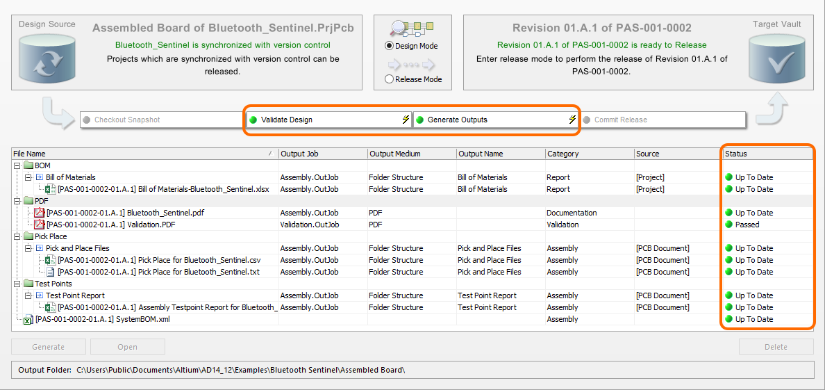
Successful trial run in Design Mode!
Actual Release - Release Mode
With success in Design Mode, let's go ahead and perform the actual release.
-
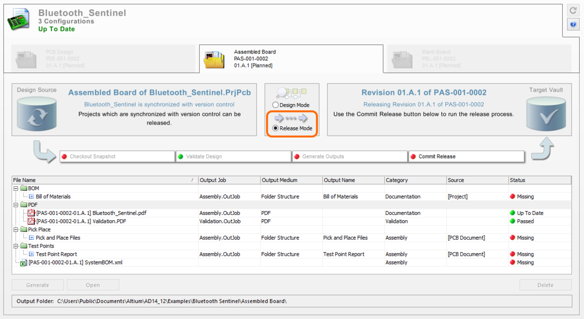
Click to select Release Mode, in the center of the PCB Release view. Once in this mode, everything becomes locked down. Only the chosen configuration of the selected design project remains enabled, with all other projects and configurations disabled. You cannot select a different configuration or jump to another project in this mode. At this point, all attention is fixed on releasing the chosen configuration with the highest integrity.
Once in Release Mode, only the chosen configuration is available to interact with.
-
To initiate the release of the
Initiate the actual release literally at the 'click of a button'.Assembled Boardconfiguration of our Bluetooth Sentinel design project, simply click the Commit Release button.
Each stage of the process flow is run in sequence – a snapshot of the design source is taken, validated, and the outputs defined in Output Job files assigned to that configuration are generated. The resulting generated data, as well as the snapshot, are then committed to the target vault. Upon committal, the Release Summary dialog will appear, providing a listing of the data that has been stored in the specified revision of the target Item in the vault.
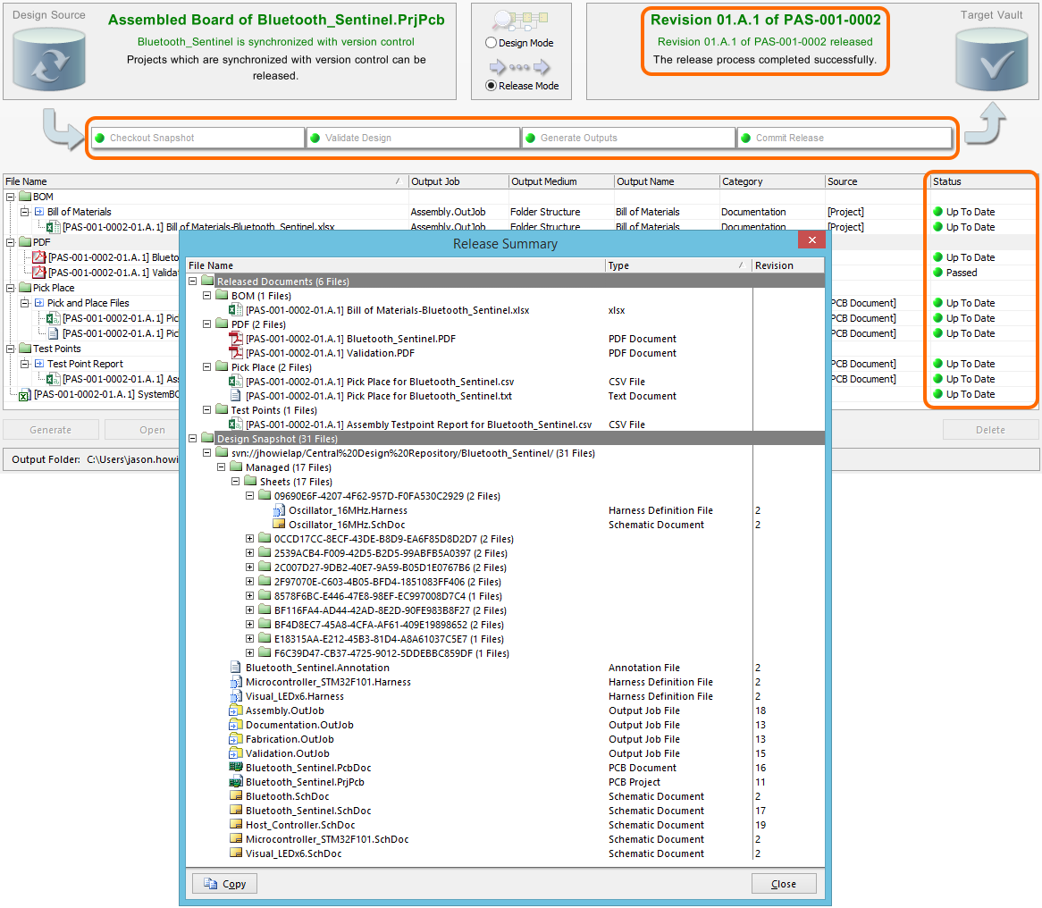
Successful release of the Assembled Board configuration of the Bluetooth Sentinel design!
As the process is fully automated, the risk of errors associated with a manual release process are no longer a consideration. Full validation, full checking. The data sent to manufacturing is exactly what it needs to be, to produce the product exactly as you designed it.
Access Released Data
Related articles: Managing Revisions and Lifecycle States - the Item View, Item Lifecycle Management
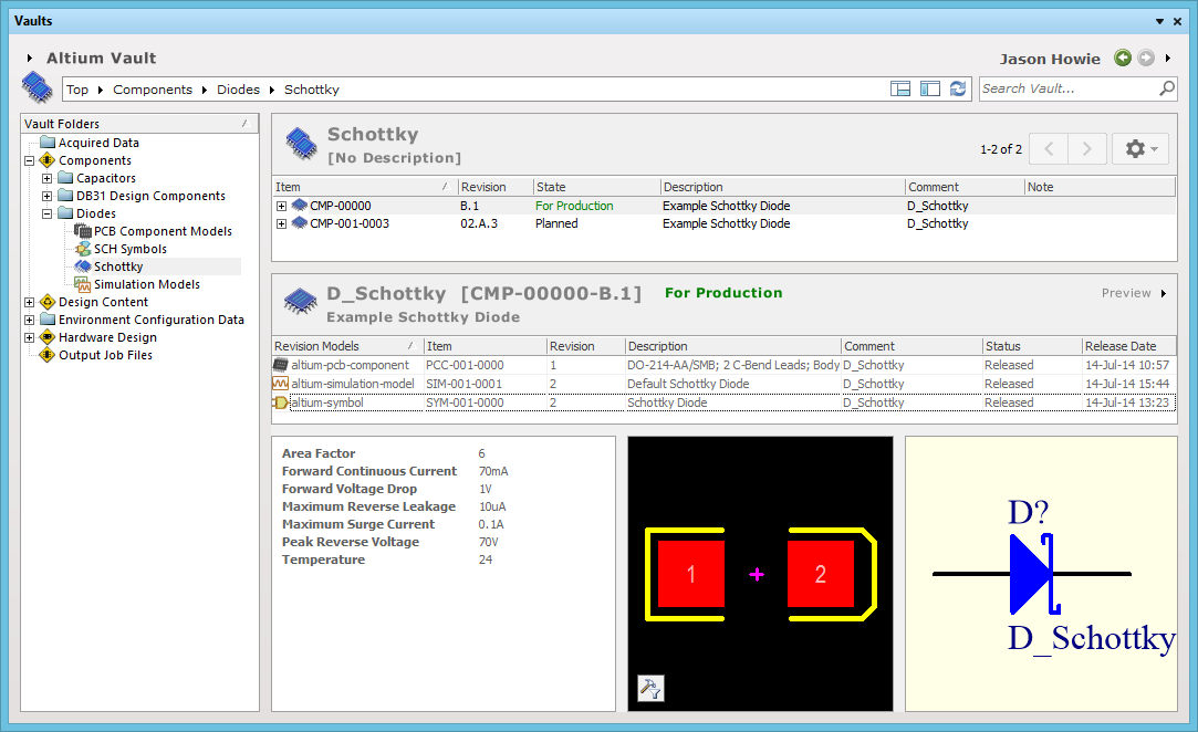
Once released, you can preview the generated data for the specific Item Revision from within the Vaults panel. The Preview aspect view presents a list of released documents, and the snapshot of the design project used to generate the release.
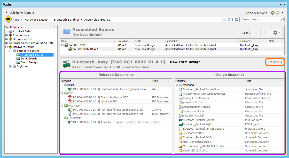
Preview the generated data for the newly released revision of the target Item in the vault, courtesy of the Vaults panel.
For a released Item, detailed information and lifecycle status controls regarding the Item (and all its revisions) are available in a dedicated Item view. This view can be accessed from the Vaults panel, by right-clicking on an Item (or Item Revision) and using the Full Item History command from the context menu. The view can also be accessed from the PCB Release view by:
- Clicking on the header text in the Target Vault region (
Revision <Revision ID> of <Item ID>). - Clicking on the Item or Revision text in the configuration tab region.
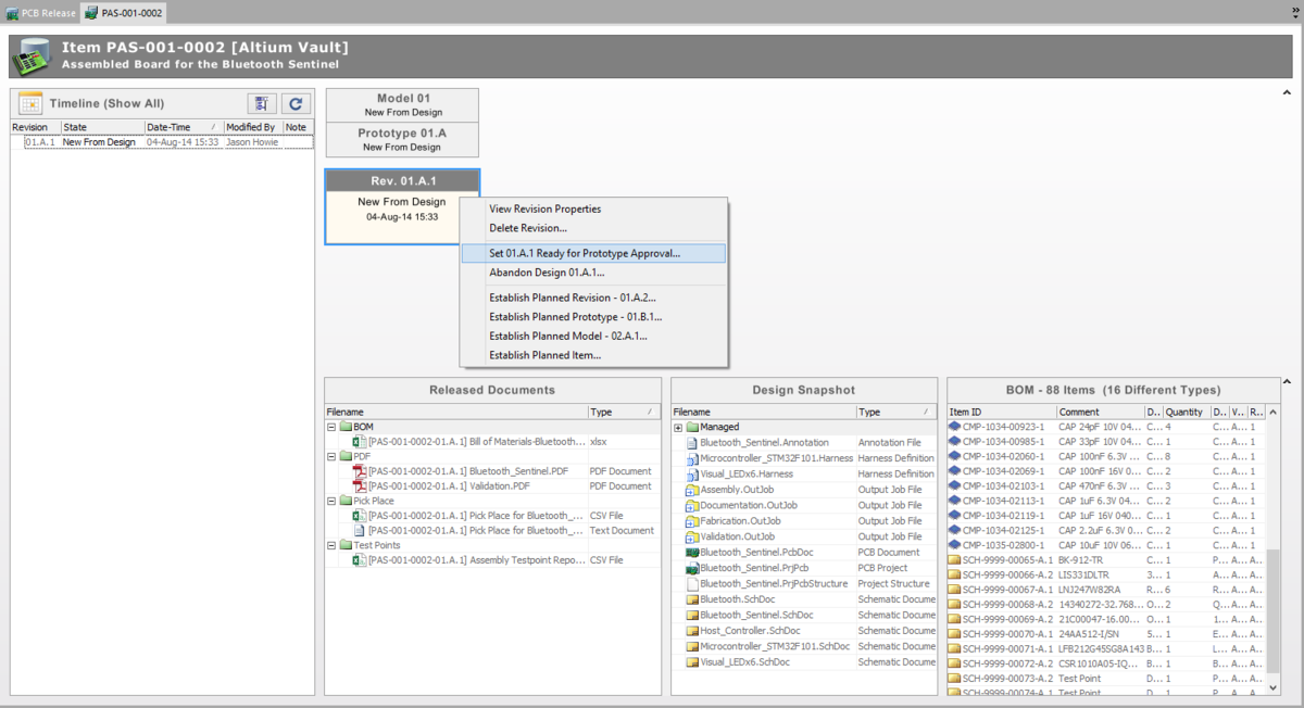
Item view for our target assembled board Item PAS-001-0002.
The Item view provides an intuitive user interface by which to visually assess the state of the Item and its revisions. Controls are provided that allow you to:
- Browse dynamically through the timeline of the Item, from initial release of data into the first revision, to the latest revision, and all revisions and state changes in-between.
- Establish a new 'Planned' revision/prototype/model of the Item.
- Manage the lifecycle state for a particular revision of the Item, in accordance with the lifecycle definition employed for revisions of that Item.
- Retrieve documents associated with each revision of the Item (generated release data and/or design snapshot).
- Publish release data directly to a nominated publishing destination.
For any revision of the Item, the view presents a preview listing of released documents, identical to that presented in the Vaults panel, as well as the System-generated BOM.