Track
Parent page: Objects
Track objects are used for routing and for general purpose drawing lines.
Summary
A Track is a primitive design object, a straight line of a defined width. Use tracks to define a straight line in the PCB workspace. Tracks are placed on a signal layer to form the electrical interconnection, or routing, between component pads. Tracks placed on a non-electrical layer are called Lines, where they are used as general-purpose drawing elements to create component outlines, instructional information, keepout boundaries, and so on. Tracks are also used in compound objects, such as dimensions.
Availability
Tracks are available for placement in both PCB editor and the PCB Library editor.
PCB Editor
In the PCB Editor different commands are used for placing tracks, depending on whether you wish place the track on a signal layer to route a connection, or place it on a non-electrical layer as a drawing-type line. Although tracks and lines are actually the same object, the difference is how the software behaves during their placement, which is why there are different commands. When a track placement command is run, such as Interactive Routing, the software monitors the click location and automatically adopts the net name of an existing object (such as a pad) under the click location. It also monitors and obeys any applicable design rules. When a line placement command is run, these monitoring behaviors do not occur.
To place Track objects:
- Click Place » Wire [P, T] from the main menus.
- Click button
 in Wiring toolbar.
To place Line objects:
- Click Place » Line [P, L] from the main menus..
- Click button from Utilities toolbar, then click button from drop down list.
PCB Library Editor
To place Line objects:
- Click Place » Line [P, L].
- Click button from PCB Lib Placement toolbar.
Placement
Regardless of which command is used (routing or line placement), the basic placement behavior is the same. After launching the command, the cursor will change to a crosshair and you will enter track placement mode. Placement is made by performing the following sequence of actions:
- Click or press Enter to anchor the starting point for the first track segment. If a routing-type placement command is being run and you click to start placement on an existing object, the track will adopt the net name of that object.
- Move the cursor to define the track segment and click or press Enter to anchor the end point for this first segment, which is also the start point for the next connected segment.
- Continue to position the cursor and click or press Enter to anchor a series of vertex points that define the series of connected track segments.
- Right-click or press Esc to end the current series of connected track segments.
Additional actions that can be performed during placement include:
- Press the * key to cycle through the available signal layers. If performing track placement a via is automatically added at each signal layer change, in accordance with the defined drill pairs and the applicable Routing Via Style design rule.
- Press the + and - keys on the numeric keypad to cycle forward and backward through all layers currently visible in the design.
- Press the Tab key to access an associated properties dialog, from where properties for the track can be changed on-the-fly.
Placement Modes
While placing track segments there are 5 available corner modes, 4 of which also have corner direction sub-modes. During placement:
- Press Shift+Spacebar to cycle through the 5 available corner modes: 45 degree, 45 degree with arc, 90 degree, 90 degree with arc, and Any Angle.
- Press Spacebar to toggle between the two corner direction sub-modes.
- When in either of the arc corner modes, hold the , or . keys to shrink or grow the arc. Hold the Shift key as you press to accelerate arc resizing.
- Press the 1 shortcut key to toggle between placing 1 segment per click (the first 5 images just below), or 2 segments per click (the last image in the set just below). In the first mode the hollow track segment is referred to as the look-ahead segment.
- Press the Backspace key to remove the last vertex.
Press Shift+Spacebar to cycle through the 5 available corner modes, press Spacebar to toggle the corner direction, press the 1 shortcut to toggle placement between 1 segment or 2 segments.
Interactive Routing and the Applicable Design Rules
During Interactive Routing the default behavior is for the software to ensure the track segments are placed in accordance with the applicable Electrical and Routing design rules. That means the software will not allow a new track segment to be placed so that it violates an existing track segment that belongs to a different net, instead it will clip the track segment to meet the design rules. This interactive routing behavior is known as the Routing Conflict Resolution mode. The default mode is Stop at First Obstacle (the current mode is displayed on the Status bar), press Shift+R to cycle to the Ignore Obstacle mode.
The term applicable design rules means all those rules that apply to the object being placed. The design rules engine works on a system where the designer writes queries that define exactly which objects they want each rule to apply to. During placement the design rules engine is queried to determine the highest priority rules that applies in the current placement situation. Rules that apply during Interactive Routing include:
- Electrical Clearance
- Routing Width
- Routing Via Style
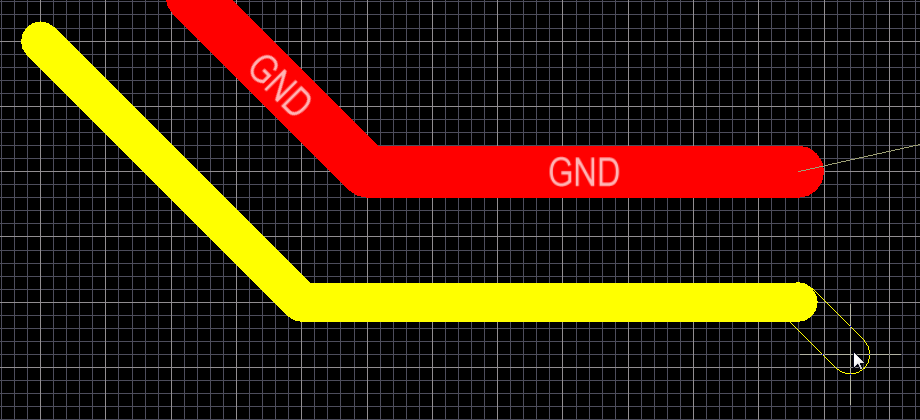
The images below demonstrate the behavior. The image on the left shows NetC9_2 being routed with a 10mil wide track, as per the applicable Routing Width design rule. The image on the right shows net GND being routed, for this net a different Routing Width design rule has been defined, with a preferred width of 20mils. Note also that the even though the cursor is over the NetC9_2 pad, the GND net is automatically being clipped to ensure the applicable Electrical Clearance design rule is being met.
The applicable routing width and clearance design rules are automatically being obeyed during interactive routing.
Non-Graphical Editing...
The following methods of non-graphical editing are available:
...via an Associated Properties Dialog
This method of editing uses the following dialog to modify the properties of a track object.
Individual track segments can be edited in the Track dialog.
The Track dialog can be accessed prior to entering placement mode, from the PCB Editor - Defaults page of the Preferences dialog (DXP » Preferences). This allows you to change the default properties for the track object, which will be applied when placing subsequent tracks.
During placement, the properties of the track or line can be edited by by pressing the Tab key.
After placement, the Track dialog can be accessed in one of the following ways:
- Double-clicking on the placed track object.
- Placing the cursor over the track object, right-clicking and choosing Properties from the context menu.
- Run command Edit » Change, then click an existing object.
...via an Inspector Panel
An Inspector panel enables the designer to interrogate and edit the properties of one or more design objects in the active document. Used in conjunction with appropriate filtering, the panel can be used to make changes to multiple objects of the same kind, from one convenient location.
...via a List Panel
A List panel allows the designer to display design objects from one or more documents in tabular format, enabling quick inspection and modification of object attributes. Used in conjunction with appropriate filtering, it enables the display of just those objects falling under the scope of the active filter – allowing the designer to target and edit multiple design objects with greater accuracy and efficiency.
Graphical Editing
This method of editing allows you to select a placed track object directly in the workspace and change its size, shape or location, graphically.
When an track object is selected, the following editing handles are available:
![]()
Selected Track
- Click and drag A to reposition the end points of the track.
- Click and drag B to change the shape of the track.

- Click anywhere on the track – away from editing handles – and drag to reposition it. While dragging, the track can be rotated or mirrored:
- Press the Spacebar to rotate the arc anti-clockwise or Shift+Spacebar for clockwise rotation. Rotation is in accordance with the value for the Rotation Step, defined on the PCB Editor – General page of thePreferences dialog.
- Press the X or Y keys to mirror the arc along the X-axis or Y-axis respectively.