Parameter
Parent page: Objects
Parameters are used for components, documents and projects to add detail information to the design.
Summary
Parameters are general purpose text strings that are child objects of a parent object, allowing detail information to be added to that parent object. For example, schematic components make extensive use of parameters, they are used to define: the Designator and the Comment; as well as the general purpose parameter strings that can be added by the designer to fully define it.General purpose component parameters can be used for a variety of functions, including: component detail, such as Wattage, Voltage, and so on; supplier detail, including the supplier name and part number; library component design detail, such as the revision number of the symbol; and documentation detail, such as a URL that links to a component datasheet.
Parameters can also be defined at the schematic sheet (document) level, and also the project level. Document-level parameters are ideal for defining fields such as the document title and number, and project-level parameters are ideal for defining fields such as the designer, or the project name.
Availability
Parameters are added as a property of the parent object, they are not placed independently like a Text String. Parameters can be added to any of the following design objects:
- Component - add user-defined parameters in the Parameters region of the Component Properties dialog, or the Library Component Properties dialog if they are being added during component definition in the Schematic Library editor. Designator and Comment parameters are always present for a Component object. To access the dialog, double-click a component in the Schematic editor, or double-click the component name in the Sch Library panel in the Schematic Library editor.
- Pin - in the Parameters tab of the Pin Properties dialog.
- Port - in the Parameters tab of the Port Properties dialog.
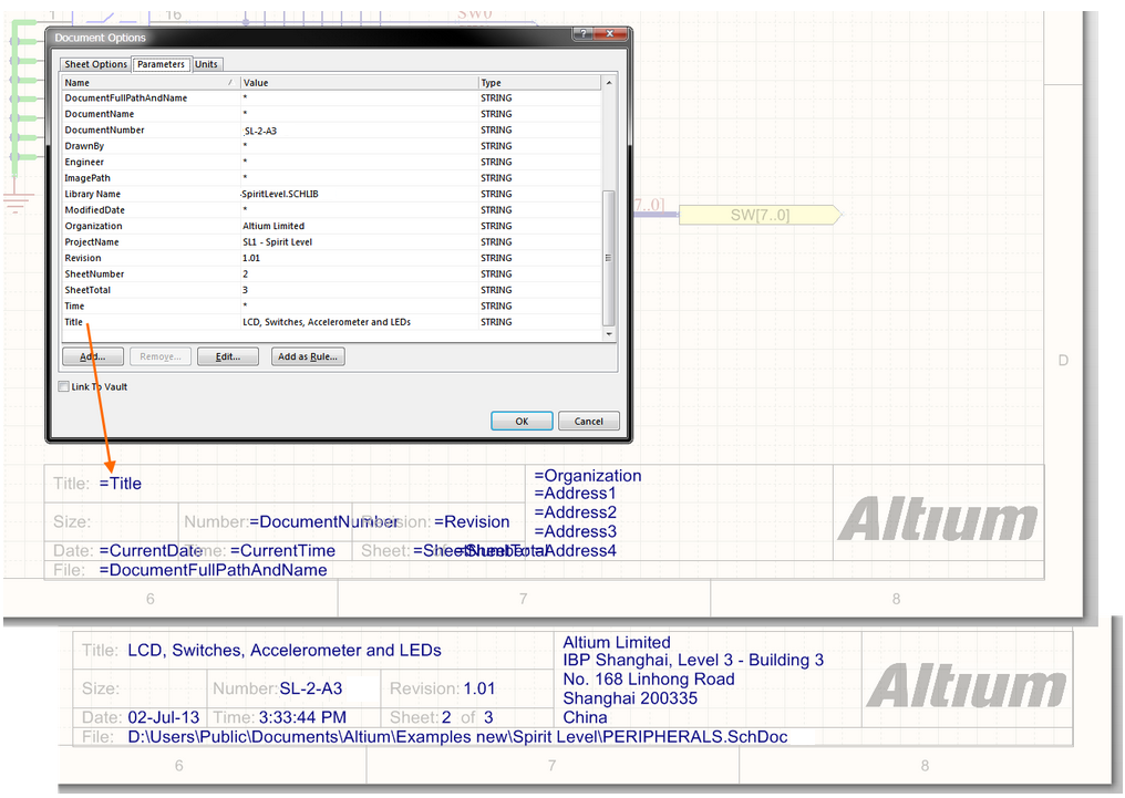
- Document - in the Document Options dialog, click Design » Document Options. Parameters are listed in the Parameters tab of the dialog, a number of default parameters are automatically included in a new schematic sheet.
- Project - in the Options for PCB Project dialog, click Project » Project Options. Parameters are listed in the Parameters tab of the dialog.
Non-Graphical Editing...
The following methods of non-graphical editing are available:
Component Parameters
Component parameters include the designator and comment, as well as any user-defined parameters.
Editing Component Parameters in the Schematic Library Editor
By default, the designator, comment and user-defined parameters are not visible in the Schematic Library editor. They are edited in the Library Component Properties dialog, double-click on the Component name in the SCH Library panel or click the Edit button to open the dialog, as shown in the image below.
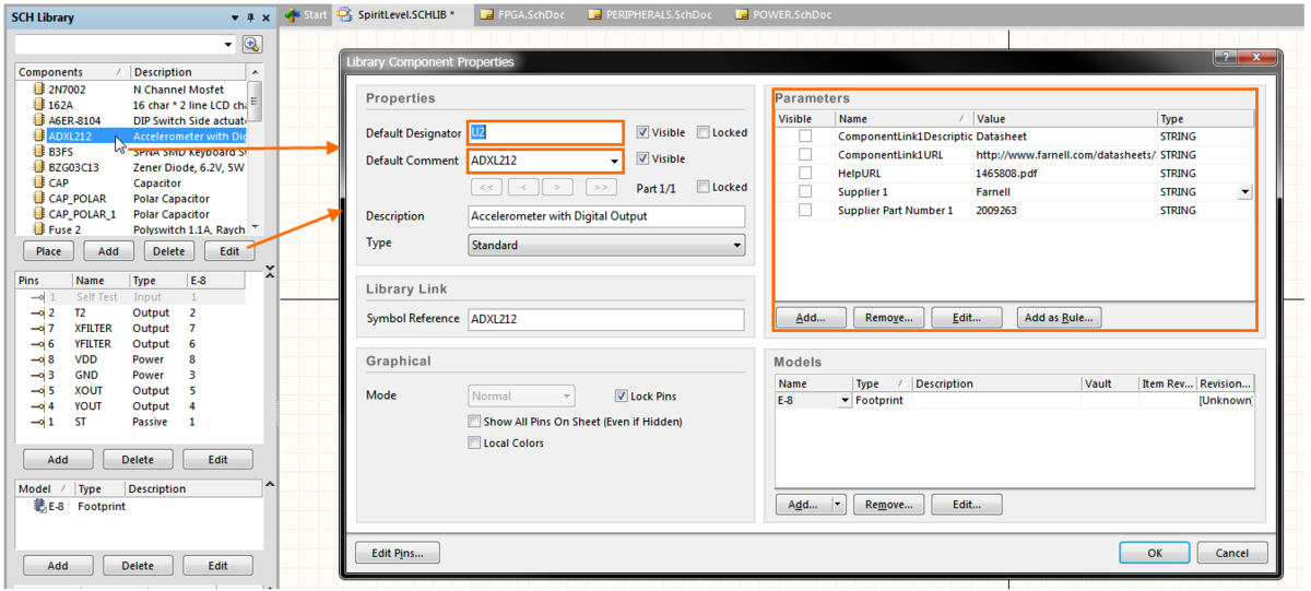
Double click on the component name, or click the Edit button, to open the dialog and edit the component parameters in the Library editor.
User-defined parameters can be displayed by enabling their Visible checkbox in the Library Component Properties dialog. Enabling this will display the parameter Value, to display the parameter name click the Edit button to open the Parameter Properties dialog where the Visible checkbox for the Name field can be enabled.
The designator and comment strings can also be displayed in the Schematic Library editor, to display them select Tools » Document Options to open the Library Editor Workspace dialog, and enable the Always Show Comment/Designator option, as shown in the image below. This setting is a property of the current Schematic Library.
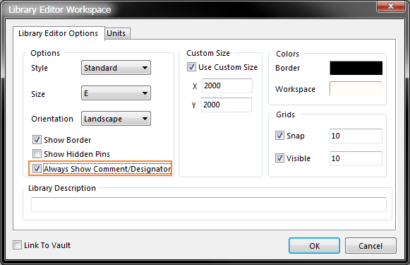
Enable the Always Show Comment/Designator option to display these strings in the Schematic Library Editor.
Editing Component Parameters in the Schematic Editor
Component parameters can be defined in the Schematic Editor as the component is being placed, or after the component has been placed on a schematic sheet.
- To define the designator/comment/user-parameter during component placement, press the Tab key while the component is floating on the cursor. The Properties for Schematic Component dialog will open, enter the required designator/comment/user-defined parameter string and click OK to close the dialog and complete the component placement. Continue to place components, or press Esc to terminate placement.
- To define the designator/comment/user-parameter after placement, double-click on the placed component to open the Properties for Schematic Component dialog where the designator/comment/user-parameter can be edited. Click OK to close the dialog and commit the change.
Editing the Display Properties of Component Parameters
The appearance of the designator/comment/user-parameter strings, which includes the font type, size and color, can be defined as:
- A software default, by setting the Designator, Comment or Parameters default settings in the Schematic - Default Primitives page of the Preferences dialog. These settings will apply unless overridden by settings defined for the component symbol.
- A property of the symbol, by setting the properties of the designator/comment/user-parameter in the Parameter Properties dialog in the Schematic Library Editor. This requires the string to be made visible, as described in the previous section.
- By editing the component designator/comment/user-parameter string of the placed schematic component - double-click on the component to edit the different parameter properties.
All 3 approaches open the Parameter Properties dialog, as shown below. Note that all properties of the parameter can be edited in this dialog.
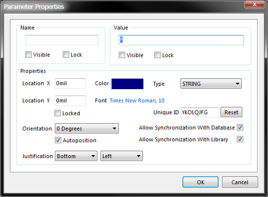
The value and the appearance a parameter string, in this case the Comment, can be edited in the Parameter Properties dialog.
Fixing the Location of Parameter Strings
The default behavior of the component parameter string is to autoposition them as a component is rotated during placement. If this behavior is not required, turn off the Autoposition option in the Parameter Properties dialog (refer to the previous image), either during symbol creation or after the component has been placed on a schematic sheet. Note that doing this sets this parameter to be classified as a manual parameter (meaning manually positioned parameter). Manual Parameters are identified by a dot on the lower left corner of their selection box. Manual parameter marker dots can be hidden by disabling the Mark Manual Parameters option in the Schematic - Graphical Editing page of the Preferences dialog, as shown below.
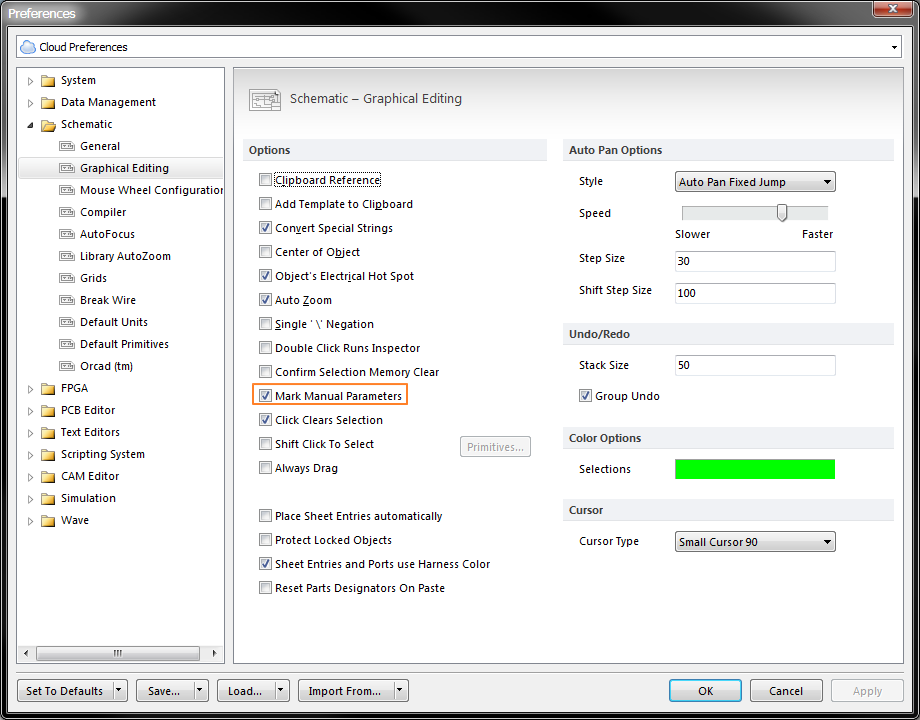

Manually positioned strings are marked by a dot, disable the display of dots in the Preferences dialog.
Special Purpose Component Parameters
Special purpose component parameters have been created for defining links from components to related documentation. These include the HelpURL, and the ComponentLink parameter pair.
The HelpURL Parameter
The HelpURL parameter allows you to define a link from a component to an external document, such as a PDF or web page. The link is activated when you press F1 over the component on the schematic sheet, or when that component in selected in the Libraries panel. Using this parameter you can reference a PDF or text file, or an HTML page. To use the feature, add the HelpURL parameter to the required component and set the value of the parameter to the document you wish to open.
When specifying the value for the parameter, you can either include an absolute path or just enter the document name. The following examples are valid entries for the value of the parameter:
C:\Design_Projects\Schematics\Modifications.txtT-33000 Getting Started with PCB Design in CircuitStudio_EN.pdfwww.altium.com
For a PDF document, you can also specify the page the document is to be opened at. This is done by adding the #page=xx option to the end of the document name, as illustrated below:
Datasheet.pdf#page=364
When F1 is pressed with the cursor hovering over the placed object, a search for the document is conducted as follows:
- If a path to is specified, this location is searched first,
- If the document cannot be found at this location, or if no path is specified, the
\Helpfolder of the CircuitStudio installation is searched, - If the document cannot be found, the default help topic for the object is displayed.
The ComponentLink Parameter Pair
This feature enables you to define and present named links to any number of reference documents. Multiple ComponentLink parameter pairs can be defined. To use this feature, add and configure the two parameters for each ComponentLink pair as follows:
First parameter - used to define the target document:
- Parameter Name =
ComponentLinknURL(where n is any integer value) - Parameter Value =
target document path\name
Second parameter - used to define the entry that appears in the menu:
- Name =
ComponentLinknDescription(where n is the same integer value used in the first parameter) - Value =
Entry to appear in the menu
Any number of ComponentLink parameter pairs can be defined, each pair is associated by sharing the same value for n.
To access component links, right-click on the placed part in the workspace, or right-click on the component in the Libraries panel. The entry for the link will appear in the References sub-menu, as shown in the image below.

The HelpURL and ComponentLink parameter pair allow support documents to be accessed from a component.
Replacing the Value of a String with a Parameter Value
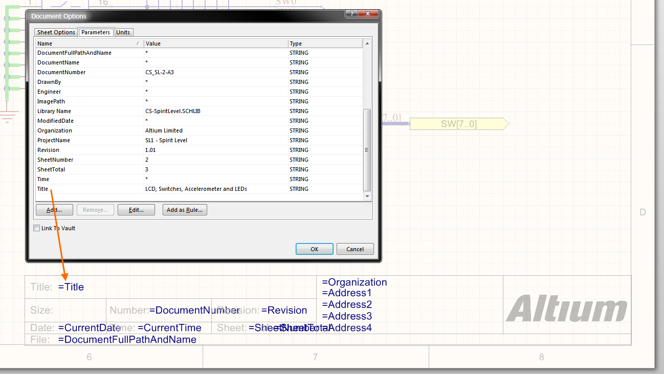
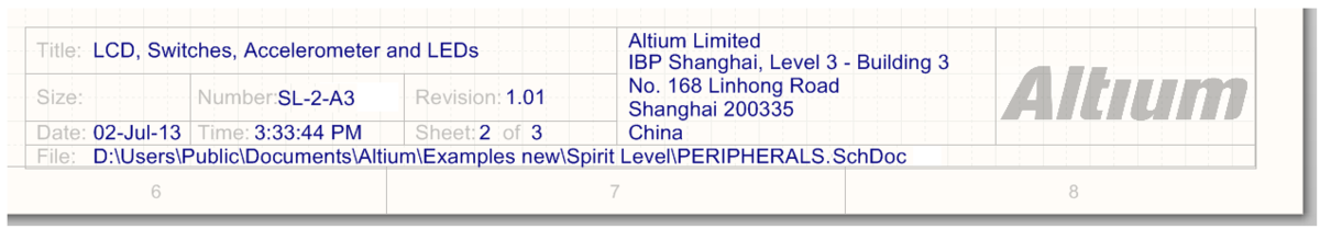
Component parameters can easily be displayed via their Visible checkbox. This is not the case for Document or Project parameters, which cannot be directly displayed on the schematic sheet. To display these parameters, a technique known as String Indirection is used. String Indirection is a system where a standard text string is placed on the schematic sheet, and instead of entering a string value, you enter the name of a Document or Project parameter preceded by an equals sign, for example =Title. The software automatically detects such strings and instead of displaying the contents of the text string, such as =Title, it checks the Document and Project parameters and if a parameter called Title is found, the value of the Title parameter is displayed.
Indirected strings are known as Special Strings in CircuitStudio. There is a large number of predefined special strings, which are listed below. Any user-defined document or project parameter can also be thought of as a special string and be indirected to a Text String on the schematic sheet.
Schematic Predefined Special Strings
The following are the predefined special strings available for use on a schematic document. The majority of these link to default parameter information defined for the active document on the Parameters tab of the Document Options dialog (Project | Content | Document Options).
=Address1– displays the value specified for the default document-level parameterAddress1.=Address2– displays the value specified for the default document-level parameterAddress2.=Address3– displays the value specified for the default document-level parameterAddress3.=Address4– displays the value specified for the default document-level parameterAddress4.=ApprovedBy– displays the value specified for the default document-level parameterApprovedBy.=Author– displays the value specified for the default document-level parameterAuthor.=CheckedBy– displays the value specified for the default document-level parameterCheckedBy.=CompanyName– displays the value specified for the default document-level parameterCompanyName.=CurrentDate– the current date, automatically calculated from the user's system settings and in the formatdd/mm/yyyy, updated upon editing the schematic or on refresh/redraw. Example:10/12/2012.=CurrentTime– the current time, automatically calculated from the user's system settings and in the formath:mm:ss AM/PM, updated upon editing the schematic or on refresh/redraw. Example:2:39:47 PM.=Date– used to display static date information. Displays the value specified for the default document-level parameterDate. Unlike the=CurrentDatespecial string, which is automatically calculated and presented in a set format, the user can enter static date information in any format they like.=DocumentFullPathAndName– used to display the full path and name of the document into which the string is placed. Example:C:\MyTestDesign\PSU.SchDoc.=DocumentName– used to display the schematic's file name only (without the file path). Example:PSU.SchDoc.=DocumentNumber– displays the value specified for the default document-level parameterDocumentNumber.=DrawnBy– displays the value specified for the default document-level parameterDrawnBy.=Engineer– displays the value specified for the default document-level parameterEngineer.=ImagePath– displays the value specified for the default document-level parameterImagePath.=ModifiedDate– the modified date stamp of the schematic, automatically populated. Example:10/12/2012.=Organization– displays the value specified for the default document-level parameter Organization.=ProjectName– displays the actual name of the project (including extension). For example, for a project with filenameMyPCB.csPrjPcb, this special string will displayMyPCB.PrjPcb.=Revision– displays the value specified for the default document-level parameterRevision.=Rule– displays the value specified for the default document-level parameterRule. The value for this parameter will initially beUndefined Rule(appearing as*on the schematic). Double-click on the parameter value to access the ability to define a rule type and edit its constraint(s).=SheetNumber– the sheet number of the current schematic.=SheetTotal– the sheet total for the project.=Time– used to display static time information. Displays the value specified for the default document-level parameterTime. Unlike the=CurrentTimespecial string, which is automatically calculated and presented in a set format, the user can enter static time information in any format they like.=Title– displays the value specified for the default document-level parameterTitle.=VersionControl_RevNumber– the current revision number of the document. Version control must be used for this string to contain any information.
Special Strings for use with Component Parameters
Several additional special strings (or special interpretations of existing ones) are available when defining component parameters. In each case, the special string is entered as the value for a parameter.
=CurrentFootprint– displays the name of the currently assigned footprint for the component, as defined in the Models region of the associated Component Properties dialog.=Comment– displays the value appearing in the component's Comment field, as defined in the Properties region of the associated Component Properties dialog.=Description– displays the value appearing in the component's Description field, as defined in the Properties region of the associated Component Properties dialog.=[ParameterName]– displays the value defined for a specified component parameter. Enter the actual name of a component parameter as the special string name – so for a component parameter namedPowerRating, simply enter=PowerRating. When defining the Comment property for a component, the associated drop-down field will be populated with special strings for all existing component parameters – enabling quick use of any defined parameter's value for the Comment.
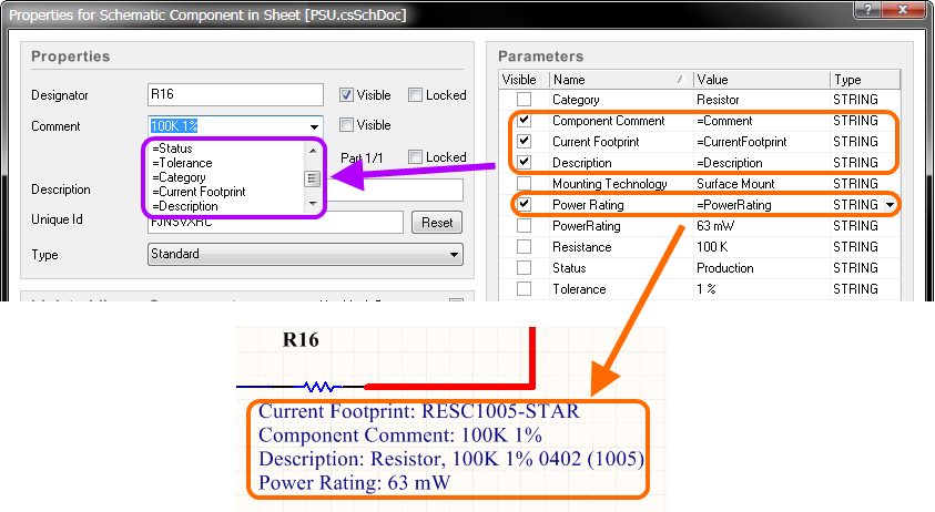
Using special strings to extract and display component parameters.
...via an Inspector Panel
An Inspector panel enables the designer to interrogate and edit the properties of one or more design objects in the active document. Used in conjunction with appropriate filtering, the panel can be used to make changes to multiple objects of the same kind, from one convenient location.
...via a List Panel
A List panel allows the designer to display design objects from one or more documents in tabular format, enabling quick inspection and modification of object attributes. Used in conjunction with appropriate filtering, it enables the display of just those objects falling under the scope of the active filter – allowing the designer to target and edit multiple design objects with greater accuracy and efficiency.
Graphical Editing
Visible strings can be edited graphically, using what is known as in-place editing. To edit a string in-place, click once to select, pause for a second, then click a second time to enter edit mode.
Click once to select the string.
Pause, then click a second time to enter in-place edit mode.
Here the string has been selected, ready to type in a replacement string.
The value of a Comment string being edited in-place.
Once editing is complete, press Enter or click away from the string to exit in-place editing mode.