Sch Editor
Contents
The Schematic Editor allows you to create, edit, check and print the schematic sheets that make up a design project. All the tools and utilities needed to perform checks for electrical and drafting violations, generate reports and create presentation quality schematic drawings are available in the editor.
Editor Environment
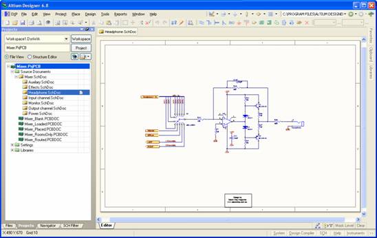
When the Schematic Editor is active i.e. a schematic document (*.SchDoc) is open and active, the main application window will contain:
- a main design window in which to capture the design
- editor-specific menus and toolbars
- workspace panels - both global and editor-specific.
Object placement, wiring and graphical editing are carried out on one or more schematic sheets, each of which appears, when opened, as a tabbed document view in the editor's main design window.

The use of the main design window in terms of actual design (placement, editing, compilation, etc) is described in detail in the section, Schematic Editing Feature Snapshots.
To learn about getting around the Schematic Editor including zooming, panning, using highlighting pens, see Getting to know your Editor
Specifying Workspace Preferences
General workspace preferences applicable to all schematic documents are defined in the Schematic section of the Preferences dialog. Choosing Tools » Schematic Preferences from the main menus will take you to the Schematic - General page of this dialog.
See Altium Designer Environment Preferences for more information
Access to Shortcuts
While capturing a design, knowledge of the various shortcuts to commonly used commands can be priceless from a productivity perspective. You can quickly peruse the shortcuts available to you keeping the Shortcuts Panel open, depending on what you are working on.
When an interactive command is running, for example placing a wire, you can access an additional pop-up menu listing all valid shortcuts for that stage of the interactive command by pressing the tilde key (~).
See Shortcut Keys for more information
Notes
The Schematic Editor can generate single sheet, multiple sheet and fully hierarchical designs of virtually any size, limited only by the available memory and storage capacity of your PC. The editor also supports true multi-channel design- often a key feature in designs destined to live in an FPGA device.
Sheet sizes include standard A-E, Orcad A-E, metric sizes A4-A0, Letter, Legal and Tabloid. You can also create your own custom sheet sizes, sheet borders and title blocks, which can be saved as templates for re-use.
A major feature of the Schematic Editor is its use of connectivity. This is the ability of the Software to recognize the physical links between objects inside the sheet and the ability to associate the logical connections that exist between various sheets in a multi-sheet design. Upon compilation of the source documents in a design project, the connective model of the design is used as the foundation for navigation using the Navigator panel.
The naming of your Compiled Document tabs is dependent on the Room Naming Style specified Project Options dialog (Project » Options » Multi-Channel).
Note that if you perform a Board Level Annotation on your project, any Room Naming Styles specified here will take precedence over your Project Options and the Compiled Document tabs will be renamed accordingly. For more information about Board Level Annotation, see Understanding Design Annotation.
Schematic Panels
To learn about the Panels available in the Schematic Editor, see Schematic Editor and Schematic Library Panels.
Certain workspace panels, although not specific to the Schematic Editor, will be used frequently when capturing your design. These include the Projects Panel, Navigator and Messages panel.
For more information on a specific panel, press F1 when the cursor is over that panel.
For a complete listing of all workspace panels, refer to the Altium Designer Panels Reference