Creating Design Rules
Contents
Parent article: Design Rules
Management of the design rules for the current board design, is performed from the PCB Rules and Constraints Editor dialog (Design » Rules). The following sections take a look at working with this dialog to browse, create, edit, and delete rules.
Browsing Rules
In the folder-tree pane on the left side of the dialog, each of the ten design rule categories are listed under the Design Rules folder. Click on this root folder to access a summary listing - in the main editing window of the dialog - of all specific rules that have been defined, for all design rule types, across all categories.
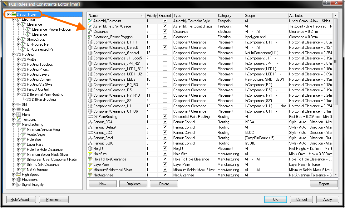
Click on the Design Rules folder to browse all defined rules for the current design.
Click on a category to list all specific rules that have been defined for all associated design rule types of that category.
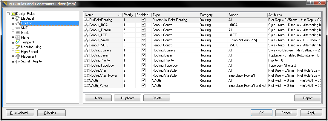
Example of browsing rules by specific category.
Click on a rule type to list all specific rules that have been defined for that type.
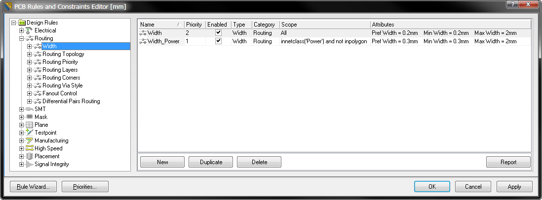
Example of browsing rules by specific rule type.
In each case - whether you have clicked on the root folder, a category or a type - the main editing window of the dialog will display the following summary information for each defined rule:
- The rule name
- The rule's priority
- Whether the rule is currently enabled or disabled (click to toggle this state)
- The type of rule it is
- The rule category it belongs to
- The scope of the rule (i.e. what object(s) it applies to)
- The constraint attributes that have been defined for the rule
Creating a New Rule
To add a new design rule from within the PCB Rules and Constraints Editor dialog, simply navigate in the tree on the left to the required rule type, and either:
- click the New button, below the rule summary list, or
- right-click and select New Rule from the context menu.
The new rule will be added to the folder-tree and will also appear in the summary list for that rule type. The rule name will appear bold to distinguish it as being new and yet to be 'applied'.
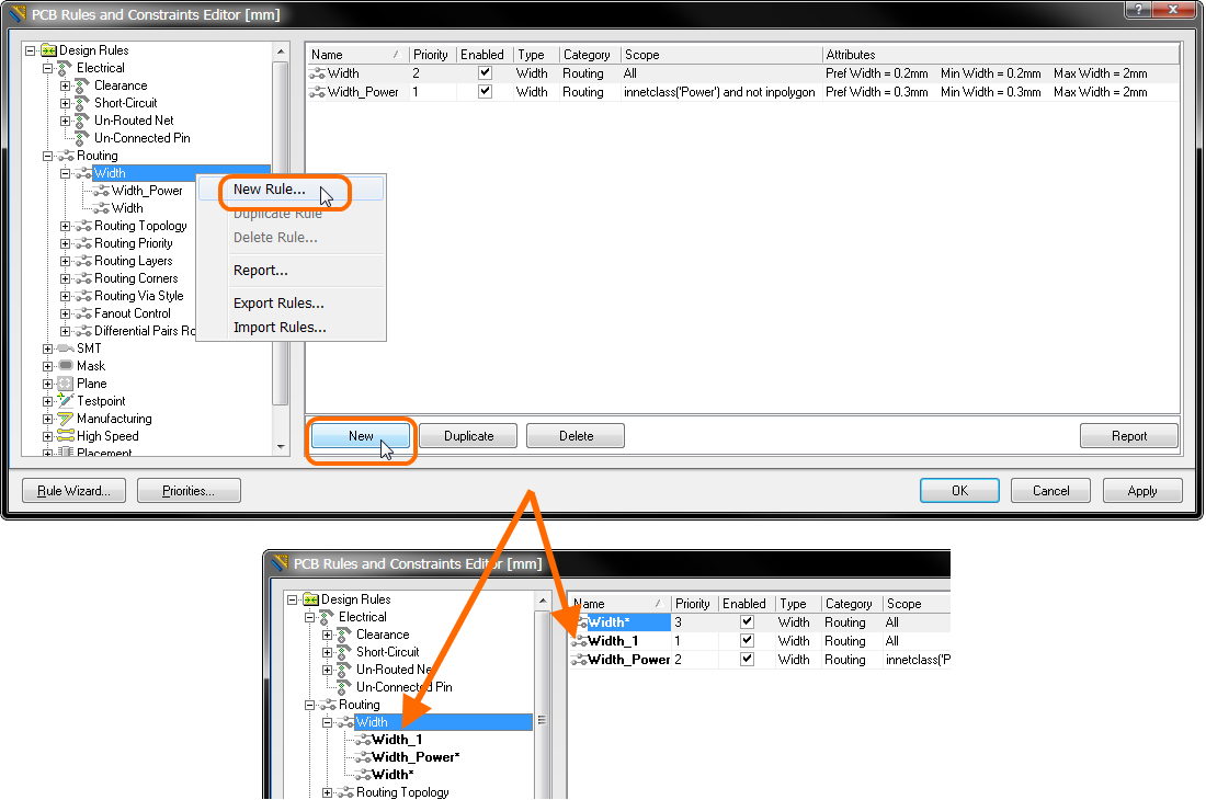
Example creation of a new PCB design rule.
When a new rule is added, it will initially be given a default name based on the specific type of rule. For example, if you add a new Clearance rule, the default name will be Clearance. If this default naming is not changed, adding another new rule of the same type will result in the same rule name with an incremented numerical suffix (i.e. Clearance_1, Clearance_2, and so on).
Creating a New Rule with the Rule Wizard
A new rule can also be created using the New Rule Wizard. Access is made directly using the Design » Rule Wizard command, or by clicking the Rule Wizard button, to the lower-left of the PCB Rules and Constraints Editor dialog.
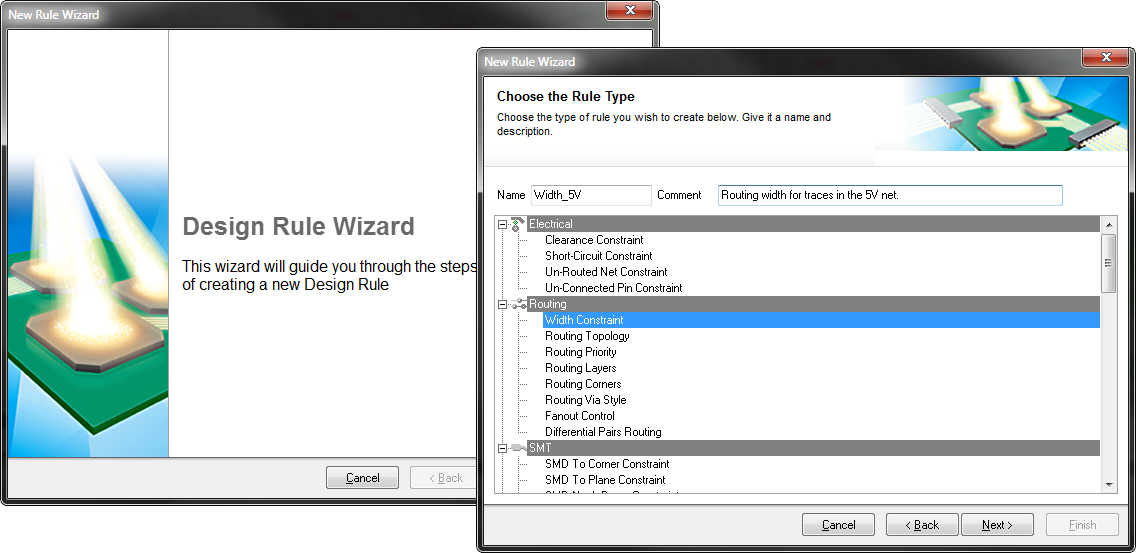
Use the New Rule Wizard to streamline rule creation.
Duplicating an Existing Rule
To quickly create an identical copy of an existing rule, use the duplicate feature. This feature can be accessed in two ways:
- Use the tree on the left to navigate to the required existing rule, right-click and choose Duplicate Rule from the context menu.
- Navigate to the specific rule type in the tree on the left, then select the rule to be duplicated in the summary list on the right. Then click the Duplicate button below the list.
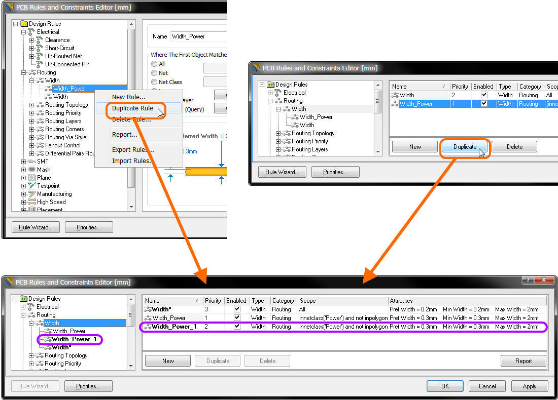
Streamline creation of similar rules using the rule duplication feature.
The duplicate rule will be named the same as the original, with the addition of a suffix (e.g. _1) to distinguish it. It's definition (scope, constraints, etc) will be identical to that of the original.
In terms of priority, it will be given the next priority below that of the original rule. So, for example, if the original rule has priority 1, the duplicate will be given priority 2.
Editing a Rule
To edit the scope and constraint attributes for a rule, either click on the entry for the rule in the folder-tree pane or double-click on its entry in a summary list. The main editing window of the dialog will change to give access to the controls for defining the scope and constraint attributes for that rule.
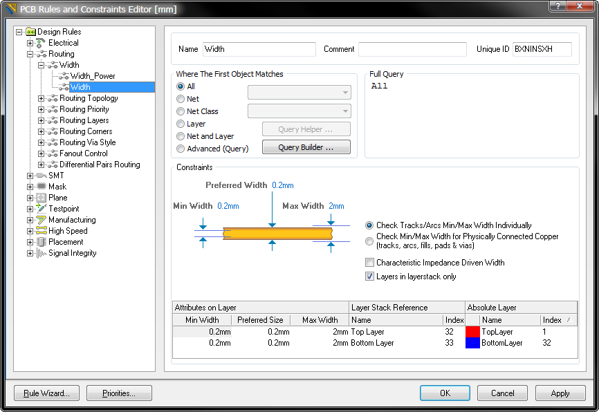
Accessing the detailed controls for the rule, including scope and constraints.
To fully define the new rule, the designer should:
- Give the rule a meaningful name to make it identifiable.
- Set the constraints of the rule.
- Define the scope of the rule by entering a query (or queries for a binary rule).
- Set the priority of the rule.
Changes made to existing rule definitions are highlighted in both the folder-tree pane and the applicable summary lists. Such entries are distinguished by the rule name becoming bold and an asterisk displayed to the right of the name. The asterisk is used to reflect that the rule is an existing rule that has been modified, rather than a newly created rule (which is displayed bold without an asterisk).
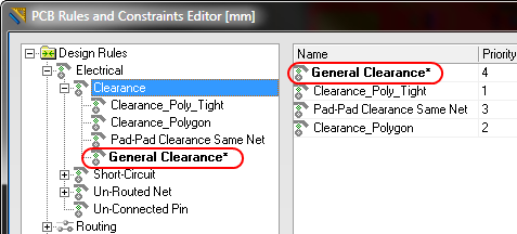
Example modified existing rule.
When a new rule is created for a particular rule type, it is automatically given priority 1. If any other rules of that type exist, their priorities will be shifted, by one, accordingly. They are then considered to be modified - even though you may not have specifically modified them at the scope/constraint level. All such existing rules of that type will therefore be displayed in the modified state (bold with asterisk)
Deleting a Rule
To delete a design rule:
- Use the tree on the left to navigate to the required existing rule, right-click and choose Delete Rule from the context menu.
- Navigate to the specific rule type in the tree on the left, then select the rule to be deleted in the summary list on the right. Then click the Delete button below the list.
The rule name will appear bold with strike-through highlighting to distinguish it as being a deletion that is yet to be 'applied'.
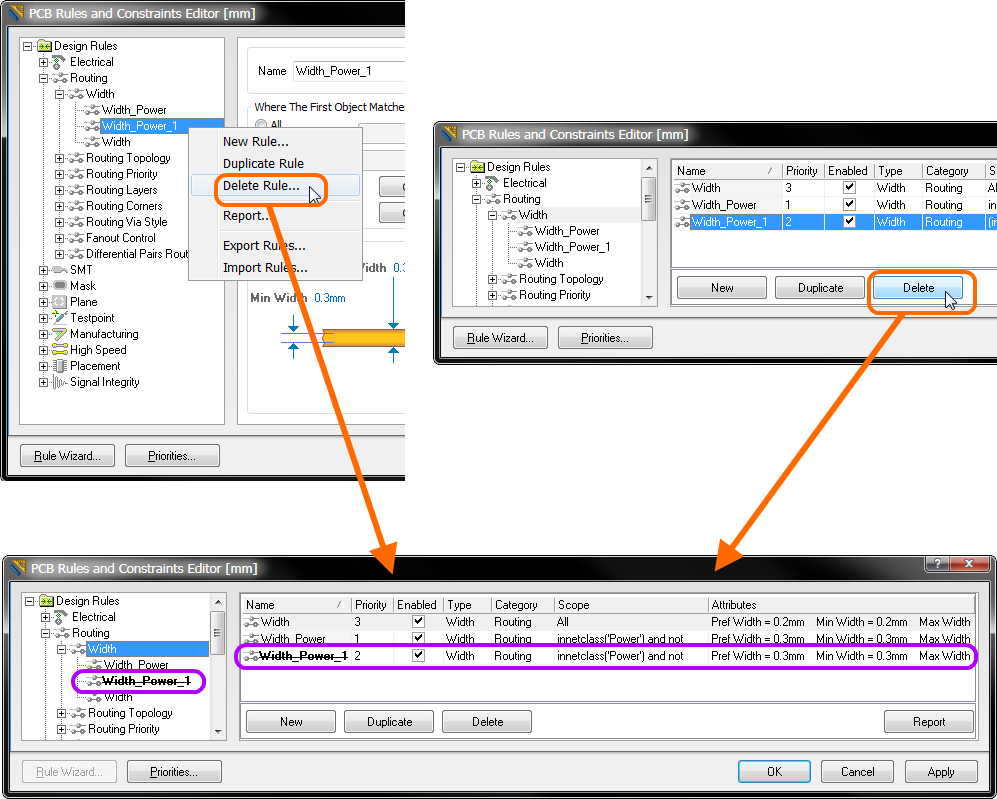
Deleting a single rule.
If a particular design rule is no longer required but may be used again in the future, rather than delete it, it can simply be disabled. Do this by toggling the corresponding Enable option for the rule in one of the relevant summary lists, on the right-hand side of the PCB Rules and Constraints Editor dialog.
Deleting Multiple Rules
Multiple rules can be deleted in a single action, from a summary list view. To do so, simply select the rules to be deleted (standard Shift+click and Ctrl+click shortcuts are supported), then click the Delete button below the list.
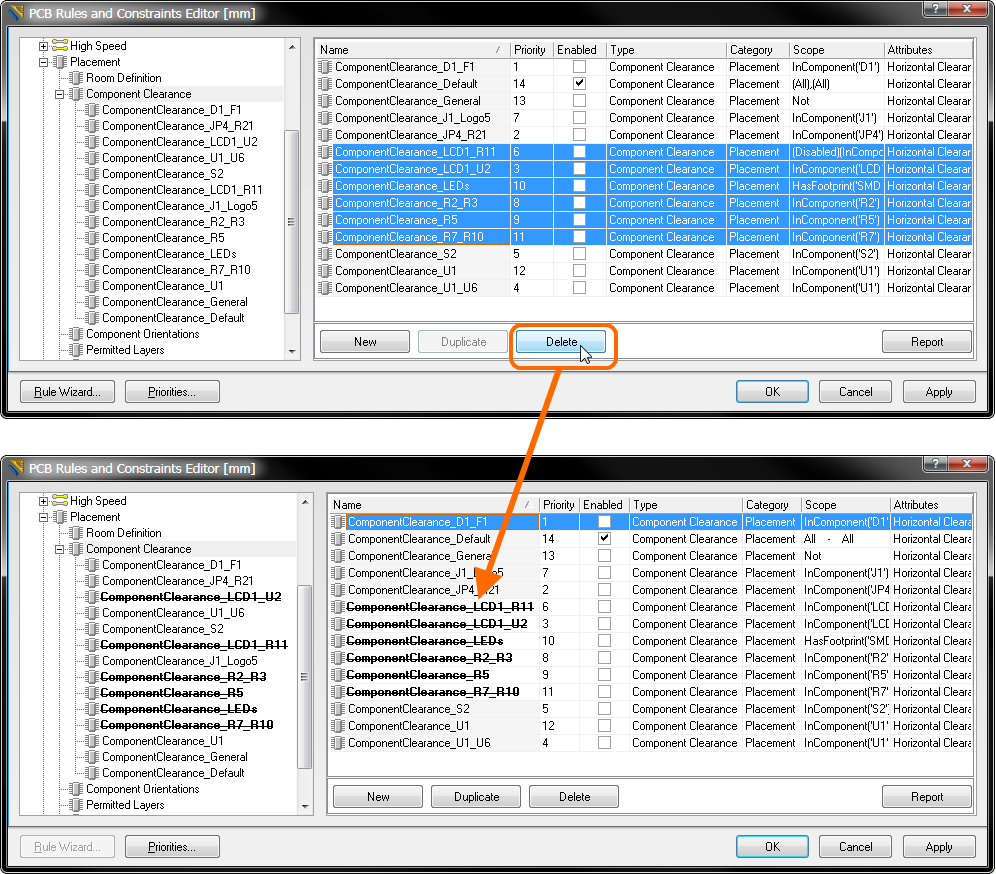
Example of multi-rule deletion in action.
Many rule types have default rules created when you open a new PCB document. In a similar fashion, if you delete all specific rules for one of those rule types, the default rule will be re-added automatically. For information on the default rules that are created, see Default Rules Created with a New PCB Document.
Effecting Rule Changes
To effect changes made in the PCB Rules and Constraints Editor dialog, either press the Apply button or press OK. Use of the former will allow you stay in the dialog to carry out further changes.