Teardrops are often added to a routed PCB design to create stronger track-to-pad, track-to-via and track-to-track connections. This is valuable when the the design objects are very small, and is particularly valuable for drilled pads and vias, because mis-alignment between the drill center and the pad/via center can result in the drill hole removing much of the copper connecting the track to the pad/via.
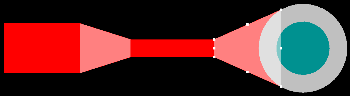
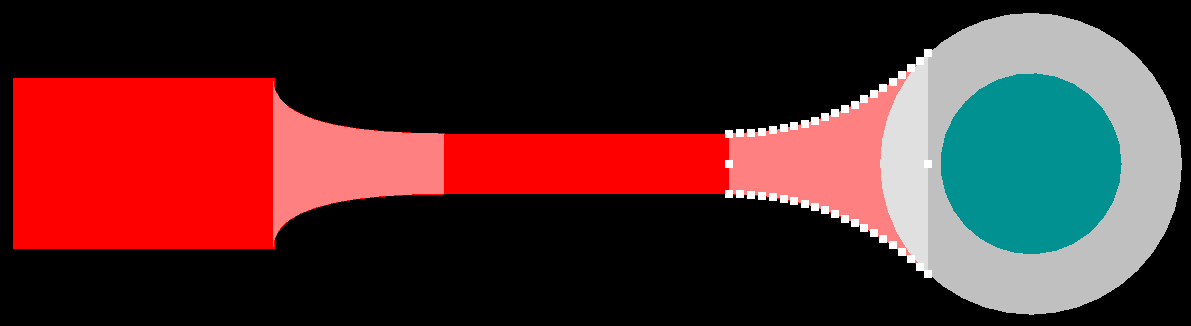
Teardrops can have straight edges or curved edges.
As can be seen in the image above, teardrops can have straight or curved edges. In earlier versions of Altium Designer, teardrops were created from a number of track or arc segments, where multiple track or arc objects were used to paint the required shape. They are now created from Region objects, requiring only one region per teardrop, which can have either straight or curved edges.
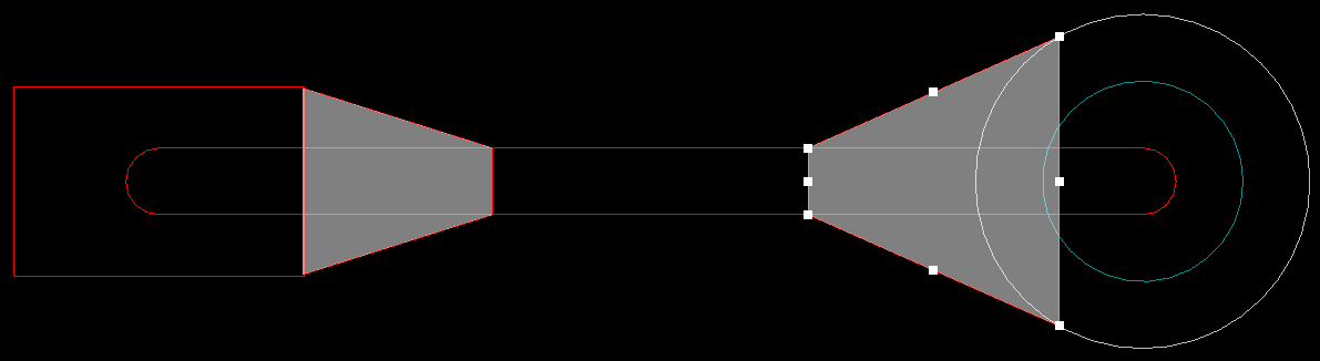
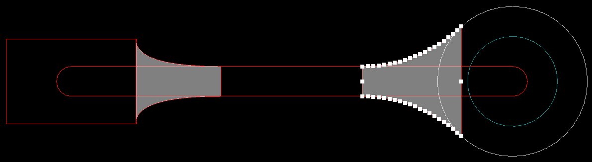
Teardrops are created from a single region object, regardless of their shape.
Adding Teardrops to a Design
Teardrops are added (or removed) by selecting Teardrops from the Tools menu. When the command is selected the Teardrops dialog will open.
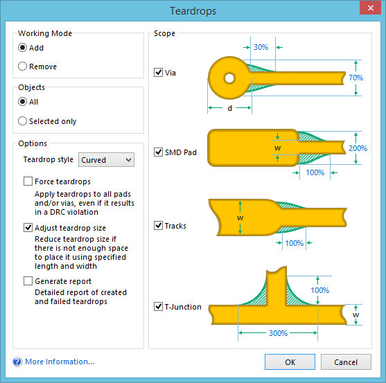
Enable the objects that require teardrops and set the options.
Teardrops can be added and their properties defined as follows:
- Working Mode - the tool can be used to both Add or Remove teardrops.
- Objects - define the coarse-level scope of teardrop addition/removal. Either consider all objects (All), or only those objects currently selected in the workspace (Selected only). This setting is used in conjunction with those object types enabled in the Scope region of the dialog.
- Teardrop style - the edge of the region object used to create the teardrop can be straight (Line) or Curved.
- Force teardrops - if this option is enabled, teardrops will be applied to all vias and/or SMD pads, even if this results in a DRC violation.
- Adjust teardrop size - if this option is enabled the teardrop size is automatically reduced to meet applicable design rules.
- Generate report - create a text report listing both successful and unsuccessful teardrop sites.
- Scope - enable which objects to consider for teardrop addition/removal - Vias, SMD Pads, Tracks, T-Junctions - in conjunction with the coarse-level scoping defined in the Objects region of the dialog. When adding teardrops, you can configure teardrop sizing as follows:
- Vias (and round Thru-Hole Pads) - specify the length and width of the teardrop as percentages of the via/thru-hole pad diameter (d). The defaults are 30% and
70%respectively. Click the blue percentage values to change these as required. - SMD Pads (and non-round Thru-Hole Pads) - specify the length and width of the teardrop as percentages of the attached track width (w). The defaults are 100% and 200% respectively. Click the blue percentage values to change these as required.
- Tracks - specify the length of the teardrop as a percentage of the attached track width (w). The default is
100%. Click the blue percentage value to change this as required. - T-Junctions - specify the length and width of the teardrop as percentages of the primary track width (w) (the horizontal track in the image). The defaults are 300% and
100%respectively. Click the blue percentage values to change these as required.
- Vias (and round Thru-Hole Pads) - specify the length and width of the teardrop as percentages of the via/thru-hole pad diameter (d). The defaults are 30% and
For more information on the dialog settings, refer to the Teardrops dialog page.
Notes
- Teardrops are automatically removed whenever an edit action is performed on either the pads/vias or the track, click and hold on a teardropped pad to observe this behavior.
- Teardrops can be re-added by re-running the Tools » Teardrops command. There is no need to remove existing teardrops before re-running the command.
- The old Teardrop tool is available if needed, select Tools » Legacy Tools » Legacy Teardrops.