Contents
Schematic wire dragging has been greatly improved in Altium Designer 14.3, with development focusing on the prevention of loss of connectivity. These improvements include:
- When dragging objects connected by parallel wiring, stairs are created to minimize the creation of auto-junctions.
- Wires are displayed correctly during drag, even if there are a few overlapping segments.
- Flickering during drag has been eliminated.
- The method of dragging net labels along with wires has been improved, so that a net label is kept attached to its wire.
- While dragging, hotspots are used to provide visual indication of where auto-junctions are going to be created.
- Unnecessary/redundant auto-junctions are removed after dragging has ceased.
- Providing visual feedback if dragging causes a connectivity change.
- Providing visual feedback when dragging multiple wire ends.
The following series of animated gifs show some of these improvements in action.
In previous versions of the software, dragging could result in lost connectivity (Left). In Altium Designer 14.3 (Right), connectivity is maintained while dragging.
In previous versions of the software, dragging could result in a net label becoming detached from its wire (Left). In Altium Designer 14.3 (Right), net labels are kept firmly with their wires when dragging.
In previous versions of the software, dragging could result in overzealous auto-junctioning, with prevalent shorting as a result (Left). In Altium Designer 14.3 (Right), 'staircasing' is used to keep parallel wiring separated, and avoid the creation of auto-junctions.
Indication of New Auto-Junction Creation
Depending on the affected wiring, performing a drag operation may result in the creation of auto-junctions at new locations. To provide visual feedback on where these new juntion instances will be, hotspots are used. Enable the use of these hotspots, and their color - for wires and buses - in the Auto-Junctions region, on the Schematic - Compiler page of the Preferences dialog.
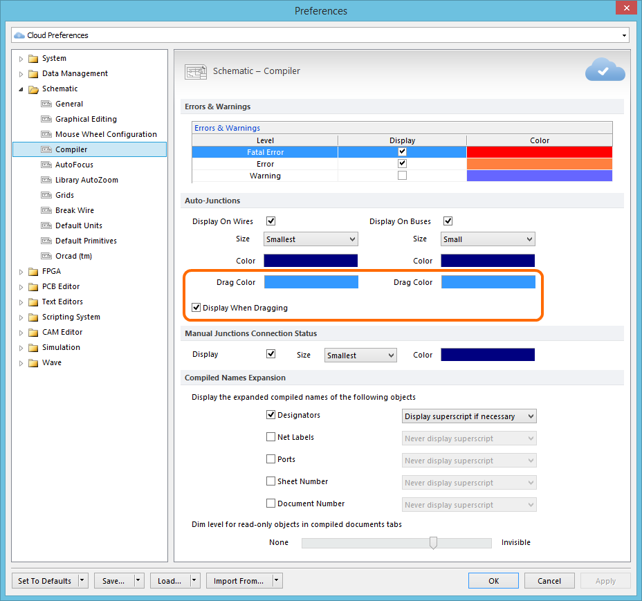
Control the display of predicted auto-junctioning during drag operations.

Example showing predicted new auto-junctions resulting from a drag operation.
Visual Indication of Connectivity Change
While dragging a component, it is possible to inadvertently drag a little to far, or off-course, resulting in an unintended auto-junction, and a potentially fatal change to the connectivity of a circuit. To provide a timely and graphical indication of the status of connectivity while performing a drag, a couple of icons are used:
![]() - OK: The drag operation is not altering the connectivity of the circuit.
- OK: The drag operation is not altering the connectivity of the circuit.
![]() - Alert: The drag operation is causing a change to the connectivity of the circuit.
- Alert: The drag operation is causing a change to the connectivity of the circuit.
The applicable icon is displayed near to the cursor as you drag.
Providing a visual warning that a drag operation will result in a change to connectivity.
Visual Feedback when Dragging Multiple Wire Ends
The multi-wire editing mode in the Schematic Editor allows you to extend multiple wires at the same time. If multiple parallel wires share a coordinate for their end vertex, then when you click and drag to move the end of one wire vertex, the end vertex of all other selected wires will also move, keeping the wire ends aligned. In previous versions of Altium Designer, while you could see and control the extension of one wire in the selection, there was no visual feedback for the ends of the other wires. They simply extended to match the wire being dragged, revealing that extension only after completing the drag process. In Altium Designer 14.3, multi-wire dragging has been enhanced to show all moving wire ends, as the drag proceeds.
In previous versions of the software, multi-wire dragging only showed extension of the single wire being dragged (Left). In Altium Designer 14.3 (Right), all moving wire ends are displayed.