Contents
Perhaps the most versatile object shape in Altium Designer are the polygonal objects. There are a number of polygonal-shaped objects, including:
- Region - this object is used to create polygonal-shaped copper regions, polygon cutouts, board cutouts and cavity definitions
- Polygon - can be created from region objects or tracks and arcs, when created from regions each isolated section of copper is a region object
- Extruded 3D Body - the plan view of an extruded 3D Body is defined as a polygonal shape
- Board Shape - after selecting the Edit Board Shape command (Board Planning Mode)
- Room - after selecting the Edit Polygonal Room Vertices command
- Via Stitching - when area constrained, the area is a polygonal shape
Editing a Polygonal Object
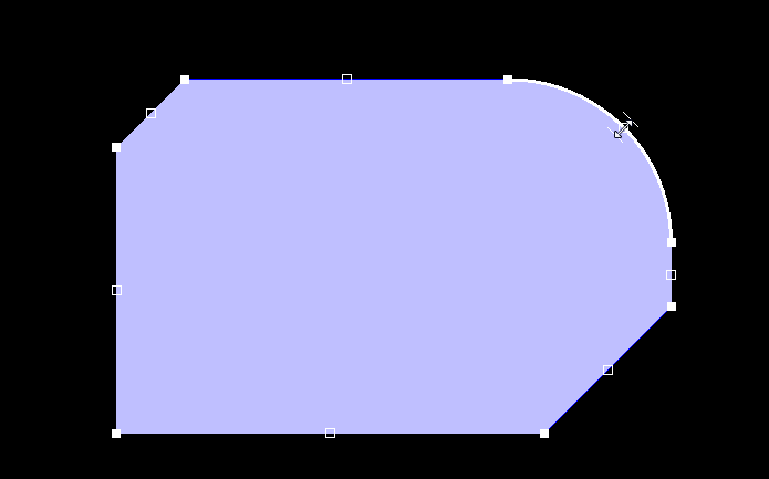
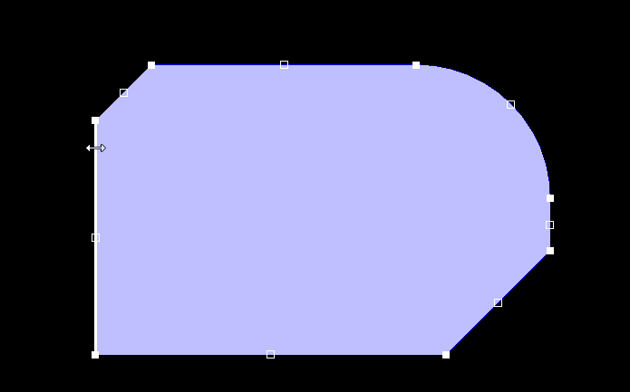
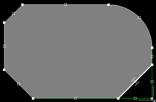
Click once on a polygonal object to select it, which puts it into edit mode. The outer shape of the polygonal object is defined by a series of edges: where each edge is represented by an end vertex at each end, shown as a solid white square; and a center vertex in the middle, shown as a hollow white square. Each end vertex represents the location where 2 edges meet, as shown in the image below.

A selected polygon ready for editing. The outer shape is defined by a series of connected edges, each edge has 2 end vertices and 1 center vertex.
Editing the Shape with Active Mouse Hover
To help the designer understand what their next edit action will do, Altium Designer gives feedback about the potential editing behavior, through a combination of the mouse cursor interacting with the object under the cursor. This behavior is referred to as Active Mouse Hover. As you hover over an edge, a center vertex, or an end vertex, both the polygon elements and the cursor change to reflect what will happen if you click and drag at that point.
What is shown will depend on the current editing mode: there are 3 editing modes available, Miter, Incurvate (arc) and Move. The current mode can be changed while dragging a vertex, press Shift+Spacebar to cycle through the 3 modes. As well as feedback being given through the Active Mouse Hover feature, the current mode is also shown on the Status bar and in the Heads-Up display.
The Heads Up Display and the Status bar include information about the current polygon editing mode.
Break Mode
In this mode, click and drag on the center vertex to break that edge into 2 edges. The Active Mouse Hover displays a double-arrow, indicating the Break mode. Note that the mouse cursor has 4 arrow heads, indicating that you can drag this vertex in all 4 directions.

Break this arc into 2 arcs.

Break this straight edge into 2 straight edges.
Incurvate (Arc) Mode
In this mode, click and drag on the center vertex to incurvate that edge. The Active Mouse Hover displays a double-bar, indicating the Incurvate mode. Note that the mouse cursor has 2 arrow heads, indicating that you can drag this vertex in 2 directions.
Incurvate this arc edge into a larger or smaller arc.


Incurvate this straight edge.
Move Mode
In this mode, click and drag on the center vertex to move that edge, maintaining the edge length. Note that the mouse cursor has 4 arrow heads, indicating that you can drag this vertex in all 4 directions.

Move this arc, maintaining its length.

Move this straight edge, maintaining its length.
Corner Vertex Behavior
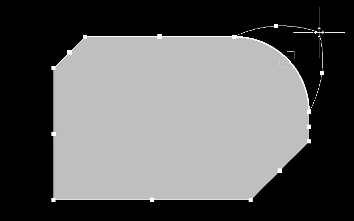
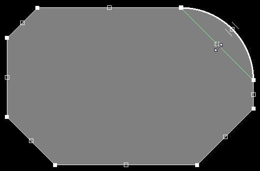
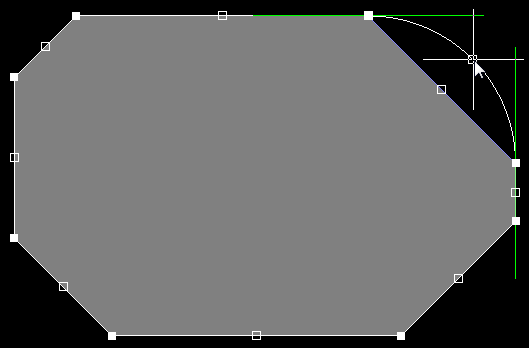
The 3 editing modes are also available when moving a corner vertex, as shown in the images below.


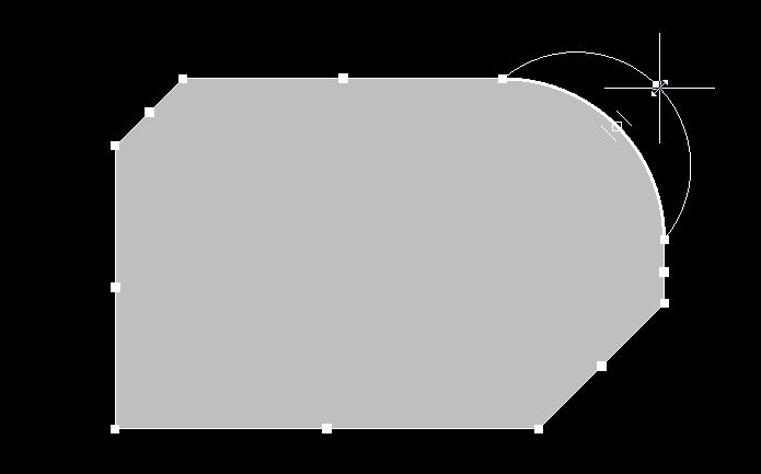
The left image shows the Active Mouse Hover over the corner vertex, the right image shows the vertex moving in Moving Vertex mode.

The left image shows the vertex moving in Mitering to Arc mode, the right image shows the vertex moving in Mitering to Segment mode.
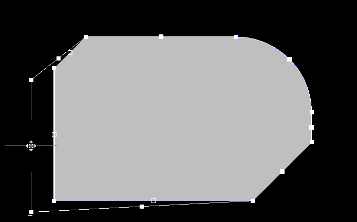
Sliding an Edge
When you hover over an edge, the Active Mouse Hover feature presents that edge as a thick white line. Click and drag on the edge to slide it, shrinking or growing the moving edge to maintain the position of adjoining edges.

Slide this arc edge, maintaining the size and position of adjoining edges.
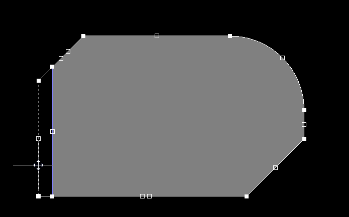
Slide this straight edge, maintaining the size and position of adjoining edges.
Adding or Deleting a Vertex
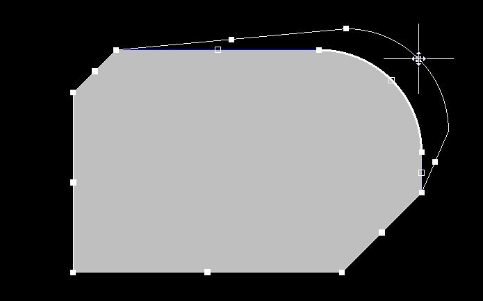
You can interactively add a vertex or delete a vertex by holding the Ctrl key and positioning the cursor in the appropriate location.
- To add a vertex, hold Ctrl then position the cursor along the edge — the Active Mouse Hover feature will show the new vertex under the cursor — click and move the cursor slightly to insert the new vertex.
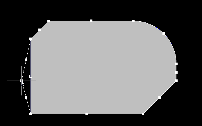
- To delete a vertex, hold Ctrl and position the cursor over the vertex to be removed — the Active Mouse Hover feature will show a white cross on the vertex — click and hold for a moment, the vertex will be removed. Alternatively, do not hold Ctrl but instead click and hold on the vertex as if you were going to move it, then press the Delete key.


Ctrl, hover and click to add a vertex (left image), or Ctrl+click on an existing vertex to delete that vertex (right image).
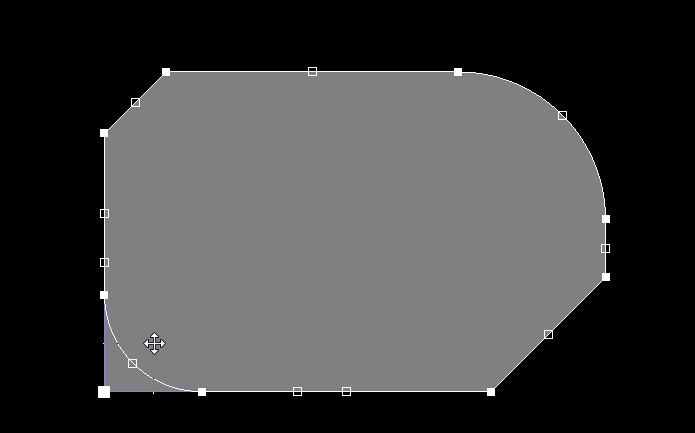
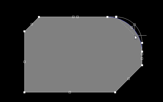
Alignment Guides
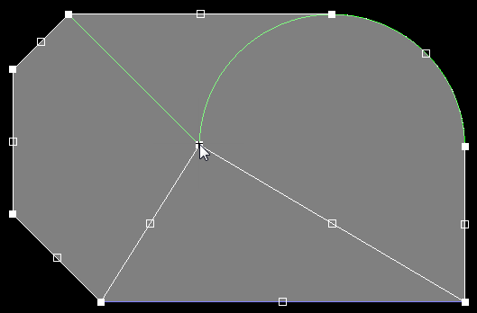
As you move a vertex around, green alignment guides will appear. These appear at useful locations, for example when the vertex location will result in the new edge aligning with an existing edge, or when an arc chord aligns with the adjacent edge. There is a slight stickiness when the guidelines appear, making it easy to maintain that vertex position.
Left - using the guideline to remove an arc (incurvate arc mode). Right - using guidelines to align new arc to existing edges.
Left - guidelines help align the breaking edge with existing edges. Right - using guidelines to align the new vertex location to existing vertices.