Automatically Necking the Routing
You can configure Altium Designer so that the routing automatically necks when it enters or exits a placement room, if that room has been used to scope a routing Width Constraint design rule. The following animations demonstrate routing out of, and into a BGA that sits within a placement room.
Width rules are obeyed, and track segments are intelligently sized as the room boundary is crossed.
Defining a Room-based Routing Rule
A room-based routing rule requires a placement room to be defined first. A placement room is also design rule. While you can create the rule and then define the room from the design rule dialog it can be more efficient to do it the other way around, interactively create the room and Altium Designer creates the design rule for you.
Creating the Room Rule
The Design » Rooms submenu has a number of room definition commands.

Rooms are a useful feature for controlling where components are placed, and also for controlling what rules are applied within that area of the board.
A room created around selected components will result in the following:
- A Component Class of the selected components is created. Review the class (Design » Classes) and update the Component Class Name as you require.
- A Placement Room Definition design rule is created. The rule is scoped to target the Component Class created in step 1, if you changed the Component Class name then the rule scope (Full Query) must be updated to match.
- The Placement Room Definition design rule is also automatically named. Update the name as required and take note of the name, because the room will be referenced in other design rules by its Name.
- If required, resize the room. To do this, click once to select it, then click and hold on a vertex to move a corner or an edge. After clicking on a vertex to move it, you can also press Shift to perform a symmetrical resize.
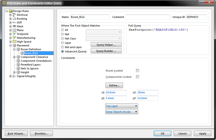
In this example the rule has been scoped to target a specific BGA footprint ('BGA50P18X18-180'), rather than a component class.
Creating the Room-based Routing Rule
Once the room has been defined, the routing width rule can then be defined. The image below show an example of a Routing Width rule that is scoped to instruct Altium Designer to set the routing width to 0.075mm whenever the routing touches the room named Room_BGA. In Altium Designer 14.3 the interactive routing engine was enhanced to automatically terminate the current track segment and start a new segment at the room boundary, to satisfy a rule such as this.
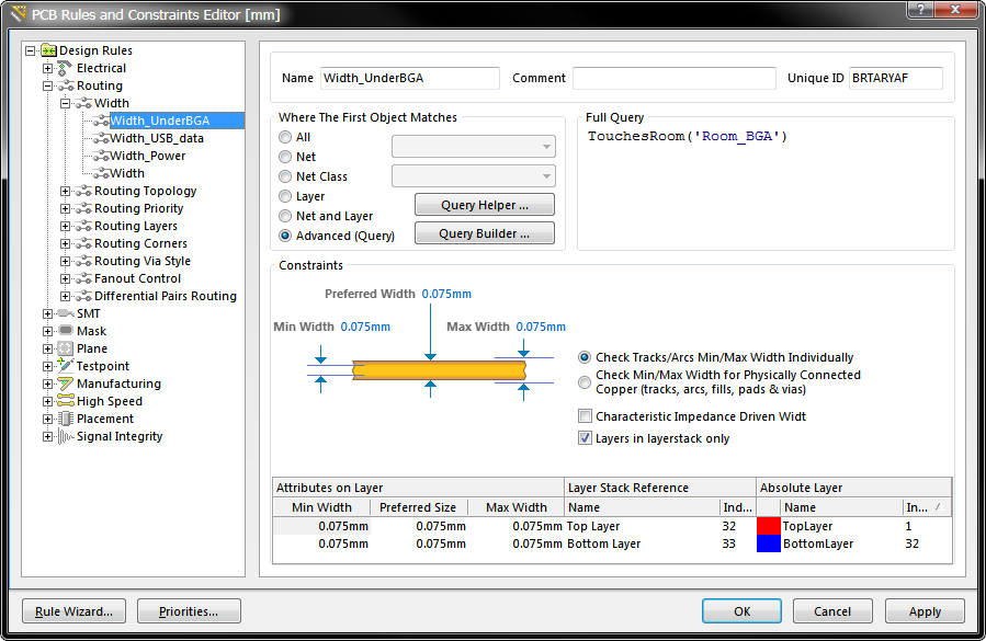
A Routing Width design rule scoped to set the width of all nets to 0.075mm within the room Room_BGA. Note that this rule appears first in the tree, indicating that it is the highest priority routing width rule.