Contents
Accordion style length tuning, also known as serpentine routing, is a standard design technique for high-speed nets with critical timing requirements. It is used to ensure that critical nets have matched lengths, by adding accordion sections to shorter route paths. Accordions are added to an existing route using the Interactive Length Tuning tool in Altium Designer. Once the command has been selected, it is simply a process of clicking and wiping over the existing route to add accordion sections.
Reshaping an Existing Accordion
To modify an existing accordion section, click once to select it and display the editing handles, as shown in the animation below. Click and drag on an edge or vertex to resize the accordion bounding region — the accordion sections are automatically resized to suit the new updated shape of the bounding region.

Resize the accordion bounding box to create the required accordion shape.
Press the Tab key while modifying the accordion shape to open the Interactive Length Tuning dialog. From here, you can change the Style, Amplitude and Gap (pitch) for the accordion in non-graphical fashion.
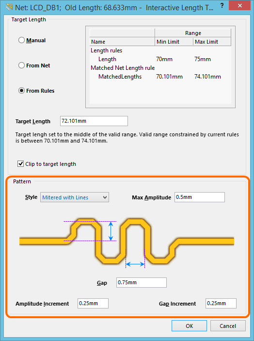
Controls related to the accordion pattern, accessed through the Interactive Length Tuning dialog.
Alternatively, as you click and hold on the accordion selection box to reshape it, you can use the following shortcuts to interactively modify the accordion's properties:
- 1 - decrease Miter Radius
- 2 - increase Miter Radius
- 3 - decrease Gap by the value specified for the Gap Increment
- 4 - increase Gap by the value specified for the Gap Increment
- , - decrease Amplitude by the value specified for the Amplitude Increment
- , - increase Amplitude by the value specified for the Amplitude Increment
- Shift+G - toggle the display of the Length Tuning Gauge
Exploding an Accordion
A length tuning accordion, being a union, is a group object - comprised of primitive track and/or arc segments. As with other group objects, such as components, coordinates, dimensions and polygons, a length tuning accordion object can be 'exploded'. In other words, it can be converted into its constituent free primitives, which can then be modified independently. To do so, use the Explode Length Tuning command, available from the main Tools » Convert sub-menu, or the right-click Unions sub-menu.
Enhanced Length Tuning Gauge
Route lengths are tuned with the aid of the Length Tuning Gauge, which can be toggled on and off using the Shift+G shortcut.
Length tuning can be performed during interactive routing - press Shift+A while routing to enable the length tuning accordion placement process. It can also be performed as a post process, by selecting the Tools » Interactive Length Tuning command.
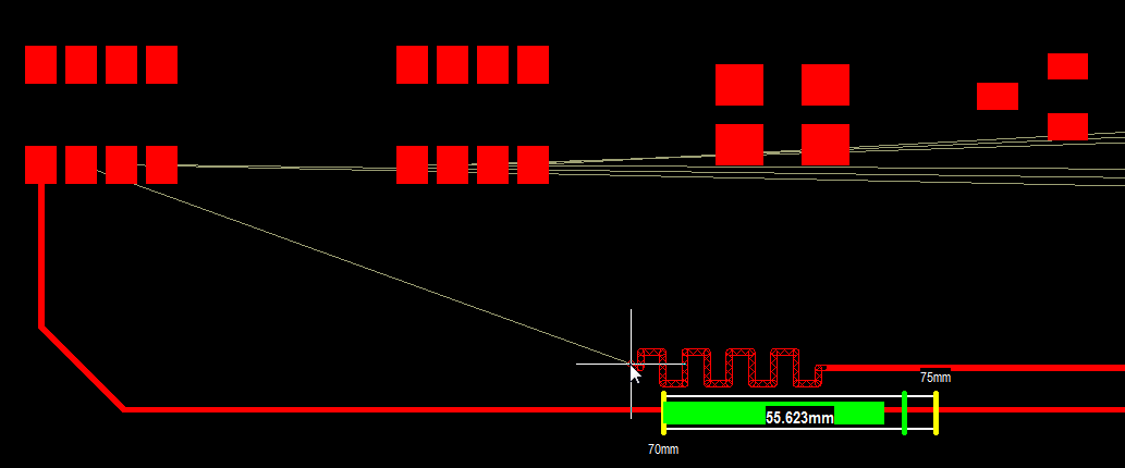
The tuning gauge display includes:
- the Min, Target and Max lengths, represented by vertical lines on the gauge
- the current route length, displayed numerically on top of the slider
- a slider, which previously represented the amount currently routed, and now represents the route length + estimated remaining length.
To enhance the effectiveness of the slider, in Altium Designer 14.3 the slider now reflects the current route length + estimated remaining length, where the estimated remaining length is the direct distance from current route end, to the target pad. The advantage of this change is that it give a much earlier indication of a net that is unlikely to meet the rule requirements.
The slider in the Length Tuning Gauge now represents the current route length + estimated remaining length.
Enhanced PCB Panel
During interactive routing the current length of a route is displayed in the PCB panel (when set to Nets mode). The default mode of the panel is to display the Name, Node Count, Routed length and Un-Routed (Manhattan) length. Right-click on the column headings to display a menu, where you can select extra columns, as well as hide existing columns. The image below shows all columns.
If there are Length design rules configured, then the routed state of each net targeted by the rule is also colored, highlighted in yellow if the route length < rule minimum, clear if the net passes the rule, or red if the route length > rule maximum.
Four nets have been routed so far - LCD_DB3 exceeds the rule and 3 other nets are shorter than the applicable Length design rule.